

Requirements:
- Raspberry Pi 2/3 with Windows 10 IoT Core Operating System connected to the internet.
- Laptop or PC with Windows 10 OS connected to the Internet.
- Visual Studio 2015 installed on your laptop or PC.
- Bread Board
- LED light
- Resistor
Follow the below steps:
Step 1: Click File, then New Project like the following screenshot,
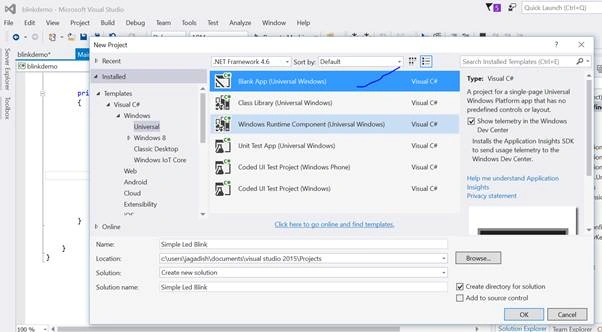 Name it Simple Led Blink.
Step 2: Right-click on the selection and add the reference,
Name it Simple Led Blink.
Step 2: Right-click on the selection and add the reference,
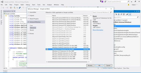 Select Windows IoT Extension for the UWP and click OK.
Step 3: Open MainPage.xaml and add the following for UI,
Select Windows IoT Extension for the UWP and click OK.
Step 3: Open MainPage.xaml and add the following for UI,
- <Grid Background="Wheat">
- <StackPanel HorizontalAlignment="Center" VerticalAlignment="Center">
- <Ellipse x:Name="LED" Fill="LightGray" Stroke="White" Width="100" Height="100" Margin="10"/>
- <TextBlock x:Name="DelayText" Text="500ms" Margin="10" TextAlignment="Center" FontSize="26.667" />
- <TextBlock x:Name="GpioStatus" Text="Waiting to initialize GPIO..." Margin="10,50,10,10" TextAlignment="Center" FontSize="26.667" />
- </StackPanel>
- </Grid>
- private const int LED_PIN =5;
- private GpioPin pin;
- private GpioPinValue pinValue;
- private DispatcherTimer timer;
- private SolidColorBrush redBrush = new SolidColorBrush(Windows.UI.Colors.Red);
- private SolidColorBrush grayBrush = new SolidColorBrush(Windows.UI.Colors.LightGray);
- public MainPage()
- {
- InitializeComponent();
- timer = new DispatcherTimer();
- timer.Interval = TimeSpan.FromMilliseconds(500);
- timer.Tick += Timer_Tick;
- InitGPIO();
- if (pin != null)
- {
- timer.Start();
- }
- }
- private void InitGPIO()
- {
- var gpio = GpioController.GetDefault();
- // Show an error if there is no GPIO controller
- if (gpio == null)
- {
- pin = null;
- GpioStatus.Text = "There is no GPIO controller on this device.";
- return;
- }
- pin = gpio.OpenPin(LED_PIN);
- pinValue = GpioPinValue.High;
- pin.Write(pinValue);
- pin.SetDriveMode(GpioPinDriveMode.Output);
- GpioStatus.Text = "GPIO pin initialized correctly.";
- }
- private void Timer_Tick(object sender, object e)
- {
- if (pinValue == GpioPinValue.High)
- {
- pinValue = GpioPinValue.Low;
- pin.Write(pinValue);
- LED.Fill = redBrush;
- }
- else
- {
- pinValue = GpioPinValue.High;
- pin.Write(pinValue);
- LED.Fill = grayBrush;
- }
- }
- }
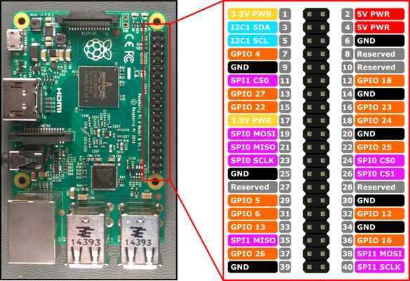
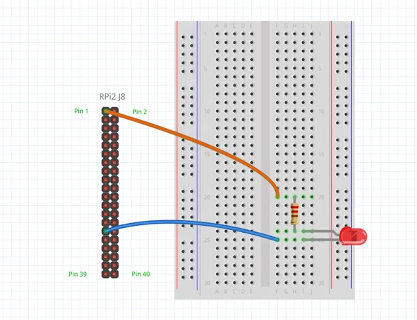
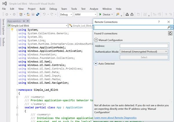
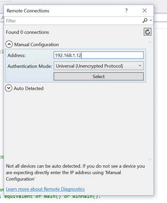
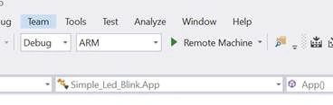
Once the application is built & run operation is completed successfully in the sense you will find the LED blinking according to the timer set.
Read more articles on Internet of Things:
Santhakumar MunuswamyPosted May 21, 2016, 2:31 AM
Thank you for nice work
Vignesh ManiPosted Apr 24, 2016, 10:24 AM
Nice
Bhuvanesh MohankumarPosted Apr 23, 2016, 6:22 PM
Good
Debasis SahaPosted Apr 23, 2016, 6:27 AM
Nice One..
NitinPosted Apr 22, 2016, 11:37 PM
Good one
Gowtham KPosted Apr 22, 2016, 1:08 PM
Good One, Thanks for sharing:)
Kuppurasu NagarajPosted Apr 22, 2016, 11:54 AM
Nice article Feroz..
Debasis SahaPosted Apr 22, 2016, 10:18 AM
Good One..
Gowtham RajamanickamPosted Apr 22, 2016, 4:29 AM
very good
Rahul Kumar SaxenaPosted Apr 22, 2016, 1:27 AM
Good show
Shakti Singh DulawatPosted Apr 22, 2016, 12:09 AM
Thanks for the article screen shot you attached are not much clear specially top two can you please try to add some zooming screen shot next time :)
Sr KarthigaPosted Apr 21, 2016, 10:54 PM
nice explanation