The BezierSegment object represents a cubic Bezier curve drawn between two lines. A cubit Bezier curve is defined by four points: a start point, an end point, and two control points.
Creating a Bezier
The BezierSegment class has three properties: Point1, Point2, and Point3, which does not include the start point of the Bezier. The start point is defined as a part of PathFigure, which is used to draw a Bezier.
The following XAML code snippet sets Point1, Point2, and Point3 properties of a BezierSegment.
<BezierSegment Point1="100,0"
Point2="200,200"
Point3="300,100" />
Loading a Bezier
A Path object is used to draw Bezier curves by setting a PathGeomerty as Path.Data. The following code snippet creates a Path and sets a BezierSegment as a part of PathFigure.Segments.
<Path Stroke="Red" StrokeThickness="2" >
<Path.Data>
<PathGeometry>
<PathGeometry.Figures>
<PathFigureCollection>
<PathFigure StartPoint="10,100">
<PathFigure.Segments>
<PathSegmentCollection>
<BezierSegment Point1="100,0"
Point2="200,200"
Point3="300,100"
/>
</PathSegmentCollection>
</PathFigure.Segments>
</PathFigure>
</PathFigureCollection>
</PathGeometry.Figures>
</PathGeometry>
</Path.Data>
</Path>
The output looks like Figure 1.
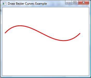
Figure 1.
Filling a Bezier
We can paint a Bezier curve by simply painting the path using the Fill method. The following code snippet change in the previous code fills a path.
<Path Stroke="Red" StrokeThickness="2" Fill="Green" >
The new output looks like Figure 2.
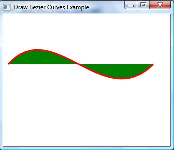
Figure 2
Now using the Bezier curves and a path, we are going to create a cool image. This image can also be that looks like Figure 3.
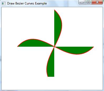
Figure 3
This is achieved by following code where you can see, we create two Bezier curves and fill them with black and blue colors. We also use TranslateTransform to move one curve to the right position.
<Path Stroke="Red" StrokeThickness="2" Fill="Green" >
<Path.RenderTransform>
<TransformGroup>
<TranslateTransform X="50" Y="50" />
</TransformGroup>
</Path.RenderTransform>
<Path.Data>
<PathGeometry>
<PathGeometry.Figures>
<PathFigureCollection>
<PathFigure StartPoint="10,100">
<PathFigure.Segments>
<PathSegmentCollection>
<BezierSegment Point1="100,0"
Point2="200,200"
Point3="300,100"
/>
</PathSegmentCollection>
</PathFigure.Segments>
</PathFigure>
</PathFigureCollection>
</PathGeometry.Figures>
</PathGeometry>
</Path.Data>
</Path>
<Path Margin="120,20,0,0" Stroke="Red" StrokeThickness="2" Fill="Green">
<Path.RenderTransform>
<TransformGroup>
<RotateTransform Angle="90" CenterX="100" CenterY="30" />
<TranslateTransform X="50" Y="50" />
</TransformGroup>
</Path.RenderTransform>
<Path.Data>
<PathGeometry>
<PathGeometry.Figures>
<PathFigureCollection>
<PathFigure StartPoint="10,100">
<PathFigure.Segments>
<PathSegmentCollection>
<BezierSegment Point1="100,0"
Point2="200,200"
Point3="300,100"
/>
</PathSegmentCollection>
</PathFigure.Segments>
</PathFigure>
</PathFigureCollection>
</PathGeometry.Figures>
</PathGeometry>
</Path.Data>
</Path>
You got the idea. Using this approach, you can draw some cool images and shapes and apply animations on them. For example, we can apply an animation on Figure 3 which can give an impression of a running fan.
Summary
In this article we discussed how to create a bezier curve in WPF using XAML.