

This article continues from Graphics in Silverlight 5 - Part I, Part II, and
Part III.
In the fourth part of this series, we shall explore the Path element.
Path
The Path element enables you to draw a series of graphic elements such as curves
and lines. The line and curve dimensions are declared through a Data property,
and are commonly specified using a mini-markup language.
The basic XAML syntax for the Path element consists of an optional FillRule
value and one or more figure descriptions.
<Path>
< object property ="[fillRule] figureDescription[ figureDescription]*" ...
/>
</Path>
A few simple elements comprising the path markup mini-language are as follows:
- figureDescription: A figure composed of a move command, draw commands, and an optional close command.
moveCommand drawCommands [ closeCommand ]
moveCommand: A move command that specifies the start point of the figure. The alphabet m is used to specify the move command. It
signifies a "move to" operation.
- drawCommands: One or more draw commands that describe the figure's contents. A draw command can consist of several shape commands. You can use one of the following shape commands: line, horizontal line, vertical line, cubic Bezier curve, quadratic Bezier curve, smooth cubic Bezier curve, smooth quadratic Bezier curve, and elliptical arc. You enter each command by using either an uppercase letter or a lowercase letter: uppercase letters denote absolute values, and lowercase letters denote relative values. The control points for a segment are relative to the end point of the preceding segment. For example, you use v and h to indicate vertical line and horizontal line respectively.
- closeCommand: An optional close command that closes the figure.
A simple example of using the Path element with above commands is shown here:
<Path Stroke="Red" StrokeThickness="4" Data="M 10,100 L 135,100 L 100,10" />
The outcome of this is shown in Figure 1.
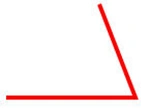
Figure 1
The following markup creates a cubic Bezier curve.
<Path Stroke="Magenta" StrokeThickness="3" Data="M 20,20 S 100,200 400,20" />
The outcome of this is shown in Figure 2.
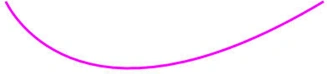
Figure 2
The following markup draws a quadratic bezier curve.
<Path Stroke="Orange"
StrokeThickness="3" Data="M 20, 60 q 50,90 0,40" />
The output is shown in Figure 3.

Figure 3
As shown so far, the Path class has a single property, Data, which accepts a
Geometry object defining one or more shapes the path includes. Geometries can be
considered to be of two types: simple geometries and complex geometries. The
LineGeometry, RectangleGeometry, and EllipseGeometry classes map directly to the
Line,Rectangle, and Ellipse shapes and are simple geometries. GeometryGroup and
PathGeometry are complex geometries. These are briefly described as follows:
- LineGeometry: Represents a straight line.
- RectangleGeometry: Represents a rectangle.
- EllipseGeometry: Represents an ellipse.
- GeometryGroup: Adds one or more Geometry objects to a single path
- PathGeometry: Is the geometry equivalent of Path and represents a more complex figure that's composed of arcs, curves, and lines.
A complex example of PathGeometry is shown
below:
<Path Stroke="DarkOliveGreen" StrokeThickness="4" >
<Path.Data>
<PathGeometry>
<PathGeometry.Figures>
<PathFigure StartPoint="50,50">
<PathFigure.Segments>
<BezierSegment Point1="100,30"
Point2="200,250"
Point3="300,150"/>
<LineSegment Point="400,10" />
<ArcSegment Size="50,50" RotationAngle="45"
IsLargeArc="True" SweepDirection="Clockwise"
Point="150,150"/>
</PathFigure.Segments>
</PathFigure>
</PathGeometry.Figures>
</PathGeometry>
</Path.Data>
</Path>
The output is shown in Figure 4.
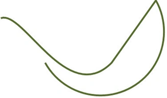
Figure 4
Conclusion: The fourth part of this series introduced the Path element.
Gowtham RajamanickamPosted May 20, 2015, 1:01 AM
good