

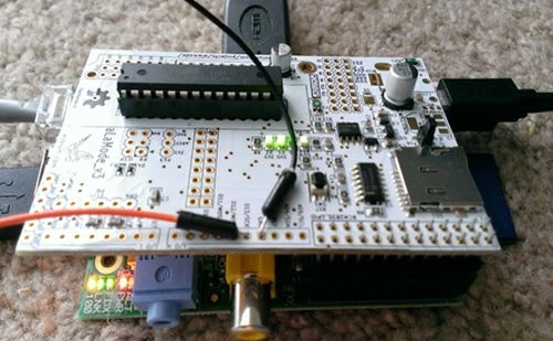
Figure 1: Arduino compatible board
Introduction
At this time, you must be wondering what Alamode is all about? It is a shield designed by the Wyolum team for Raspberry PI.
To understand in a much simpler way, it’s a shield that sits on top of Raspberry Pi. The Alamode interfaces with the Raspberry Pi via I2C, SPI or Serial UART. The heart of Alamode is ATMEGA328P-PU, which is an 8-bit Microcontroller with a 32KB In-system flash runs on 20MHz with a voltage of 1.8V-5.5V.
Alamode is an Arduino compatible board or a shield for Raspberry Pi. The alamode includes the following:
- ATMEGA328P 8bit microcontroller
- Precision real-time clock (RTC)
- Micro SD card reader
- Reset button
- Standard shield headers
Those who have programmed with Arduino would have understood by this time, the alamode is nothing but an Arduino compatible clone. The alamode microcontroller is loaded with an Arduino Uno (optiboot_atmega328.hex) boot loader.
We will see in brief about the underlying things about the alamode. Since it‘s based on the Arduino platform, you have to code the Arduino sketches and then upload the same to alamode. We will be setting up the alamode to install Arduino IDE and then we will have a look into other configurations that are required for the Raspberry PI and Alamode communication using the serial interface.
If you are curious to know the program which is responsible for uploading the hex file contents of your sketches to Arduino, then you will have to take a look into the link for avrdude documentation. Yes, it is the avrdude, an executable which is a program for downloading and uploading the on-chip memories of Atmel’s AVR microcontrollers which are also being used by alamode.
The alamode uses 5v power, you can either go with external power supply or it can be powered from Raspberry PI. There is an option for that and one should be careful in enabling the 5V link option. The alamode can be programmed in a similar way that one used to do with Arduino. Coming next, we will see how to set up and use alamode and program the same.
Note: When you are dealing with a low power application, then you can power the alamode through Raspberry Pi. Say if you are working on a simple LED project, then it’s good to go with the Raspberry Pi’s internal power. If you are connecting the shield and working on some complex projects, make sure to power up the Alamode with a 5V power supply.
We will be discussing the following mentioned points about Alamode:
- Why Alamode?
- Setting up Alamode for Raspberry PI
- Behind the scene of Alamode
- Demo Code
- Common Problems
- Why Alamode?
Let us see why you want to go with alamode. The following are some of the key things that I have listed, it is useful in many ways:
- Inbuilt high precision real-time clock with an integrated temperature-compensated crystal oscillator.
- Supports built-in micro SD card reader. You can make use of it to read and write some useful information.
- One can make use of the alamode analog pins and program with Arduino sensors.
- Supports all Arduino Uno and standard compatible shields.
- In build GPS support for the Fastrax UP501 module.
- Interface with Raspberry PI via I2C, SPI or Serial UART.
More information about the Alamode can be found at:
Setting up Alamode for Raspberry PI
Let us see how to setup alamode for Raspberry PI (Model B or B+).
The alamode works with Noobs or the Rasbian operating system. If you wish to download the latest rasbian, follow this link.
Run the following commands to install Arduino on Raspberry PI.
- $ sudo apt-get update
- $ sudo apt-get install arduino
- $wget http://git.io/alamode-setup
- $ tar -xvzf alamode-setup.tar
- $ cd alamode-setup
- $ sudo ./setup
- $sudo nano /etc/inittab
- #T0:23:respawn:/sbin/getty -L ttyAMA0 115200 vt100
- console=ttyAMA0, 115200 kgdboc=ttyAMA0,115200
- sed -i'bk' -e's/console=ttyAMA0,115200.//' -e's/kgdboc=tty.*00.//' /boot/cmdline.txt
- sed -i'bk' -e'/T0.*ttyAMA0.*vt100/s/T0/#T0/' /etc/inittab
- rm /etc/inittabbk
- cp avrdude /usr/bin/avrdude
- cp avrdude /usr/share/arduino/hardware/tools
- cp avrdude.conf /usr/share/arduino/hardware/tools
- cp boards.txt /usr/share/arduino/hardware/arduino
- alamode.name=AlaMode
- alamode.upload.protocol=alamode
- alamode.upload.maximum_size=32256
- alamode.upload.speed=115200
- alamode.bootloader.low_fuses=0xff
- alamode.bootloader.high_fuses=0xde
- alamode.bootloader.extended_fuses=0x05
- alamode.bootloader.path=optiboot
- alamode.bootloader.file=optiboot_atmega328.hex
- alamode.bootloader.unlock_bits=0x3F
- alamode.bootloader.lock_bits=0x0F
- alamode.build.mcu=atmega328p
- alamode.build.f_cpu=16000000L
- alamode.build.core=arduino
- alamode.build.variant=standard
- KERNEL=="ttyAMA0", SYMLINK+="ttyS0",GROUP="dialout",MODE:=0666
- KERNEL=="ttyACM0", SYMLINK+="ttyS1",GROUP="dialout",MODE:=0666
- cp 80-alamode.rules /etc/udev/rules.d
- chown root /usr/bin/avrdude /usr/share/arduino/hardware/tools/avrdude
- chgrp root /usr/bin/avrdude /usr/share/arduino/hardware/tools/avrdude
- chmod a+s /usr/bin/avrdude /usr/share/arduino/hardware/tools/avrdude
Here’ the code snippet of blink sketch.
- /*
- Blink
- Turns on an LED for one second, then off for one second, repeatedly.
- Most Arduinos have an on-board LED you can control. On the Uno and
- Leonardo, it is attached to digital pin 13. If you're unsure what
- pin the on-board LED is connected to on your Arduino model, check
- the documentation at http://arduino.cc
- This example code is in the public domain.
- modified 8 May 2014
- by Scott Fitzgerald
- */
- // the setup function runs once when you press reset or power the board
- void setup()
- {
- // initialize digital pin 13 as an output.
- pinMode(13, OUTPUT);
- }
- // the loop function runs over and over again forever
- void loop()
- {
- digitalWrite(13, HIGH); // turn the LED on (HIGH is the voltage level)
- delay(1000); // wait for a second
- digitalWrite(13, LOW); // turn the LED off by making the voltage LOW
- delay(1000); // wait for a second
- }
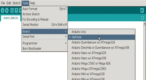
Common Problems
These are some common problems as stated on the following website,
- One common problem which you might encounter while uploading the sketch is:
avrdude: ser_recv(): programmer is not responding.avrdude: stk500_recv(): programmer is not responding.This happens for various reasons. If you wish to know more information about the problem, under Arduino preferences, you can set the show verbose output during upload so that should give more information about the problem. I had encountered a similar issue, the microcontroller was unable to respond during the upload and there wasn’t an issue with the Alamode but I later realized the fact that the GPIO pins of Alamode were not rightly in place with the Raspberry Pi. There was a slight gap and I happened to slant the Alamode a bit so that the Raspberry PI’s GPIO is fully in contact with the Alamode.
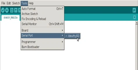
- There are cases where the serial port is in use, in such cases, you won’t be uploading the sketch. Make sure the serial port /dev/ttyS0 is not in use while you are uploading the sketch.
- There are times you are unable to select the serial port from Arduino IDE.
Points of Interest
I am not an expert in the electronics field and neither it’s my specialization. What I have mentioned in this article is the result of my research and learning as a part of IoT. Please correct me if I am wrong or things need to be improved.
The alamode itself is an interesting interfacing shield for Raspberry Pi. This small shield has opened up ideas for building things in IoT as it brings us more opportunities to use a microcontroller to program and deal with various sensors and shields that one can connect to it. One can simply build applications both on Raspberry PI microprocessor and Alamode’s microcontroller and communicate with each other through Raspberry PI’s GPIO serial interface. What was missing in Raspberry PI is all provided through this small little shield - The Alamode.
Gowtham RajamanickamPosted Apr 26, 2016, 8:38 AM
good one..
Sr KarthigaPosted Feb 14, 2016, 7:50 AM
Good one sir
Nilesh JadavPosted Oct 30, 2015, 11:50 AM
Good post !
Harshad PansuriyaPosted Oct 30, 2015, 7:16 AM
Nice one