
Introduction
Today, we'll study the basics of the ESP-12E NodeMcu V3 module. We will also see the basic connection scheme for blinking-led using Arduino IDE later in this tutorial.
Q>> What is an ESP-12E NodeMcu V3 module?
A>> NodeMCU is an LUA based interactive firmware for Expressif ESP8622 Wi-Fi SoC, as well as an open-source hardware board that, unlike the $3 ESP8266 Wi-Fi modules, includes a CP2102 TTL to USB chip for programming and debugging, is breadboard-friendly, and can simply be powered via its micro USB port.
This module is one of the cheapest available wifi-modules in market. V3 or Version3 is the latest version of this module. This tutorial, however, will facilitate you to connect all the versions of ESP8266 NodeMcu, i.e V1, V2 or V3.
For makers, having ESP-12 module, rest assured, 12E is no different from its precursor. The only difference: 6 extra GPIOs are present in ESP-12E
- Headers: 15-pin header with access to GPIOs, SPI, UART, ADC, and power pins.
- Power: 5V via micro USB port
Hardware Components required:
ESP 12E NodeMcu V3, A breadboard for placing the LED and a couple of Jumper wires to connect them.
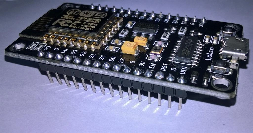
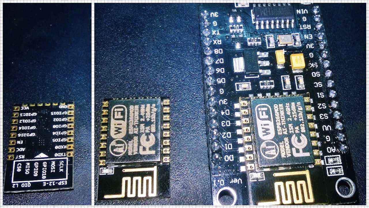
This NodeMcu breakout module is built around ESP-12E board
Software required: Arduino (In a future tutorial, we'll see how to work in Lua)
But, since most of us are familiar with ArduinoIDE, let's ponder upon this for a while.
Header PINOUT: (Save this picture for future references)
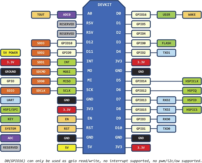
NodeMcu header pin-out
After you've assembled all the hardware components, click on this link and download all the files. The file contains requisite drivers needed to use this module. This will save you a lot of time.
Now, the ZIP file you've just downloaded, will be put to use in this tutorial as well as in the forthcoming tutorials.
Well, it's very simple!
First of all, your ArduinoIDE needs to know that you want to use this NodeMcu module. That is, you need to select the right board. Confused? Follow this flowchart: (Tools, Board, then Boards Manager).
.png?w=1280&h=960&fit=max)
Next, select the requisite board.
.png?w=1280&h=960&fit=max)
Out of this entire list, you need to select "NodeMCU 1.0 (ESP-12E Module)" as in the figure below:


Now, select the correct port. Can't recognize the port?? Wait!
Check this out.....
Go to the Device Manager and update the driver. (Follow the GIF below)
Now, its a matter of few minutes before you can get started.... Let's proceed.
Connecting the LED to NodeMcu: (Zoomed-snapshot of the Circuit)
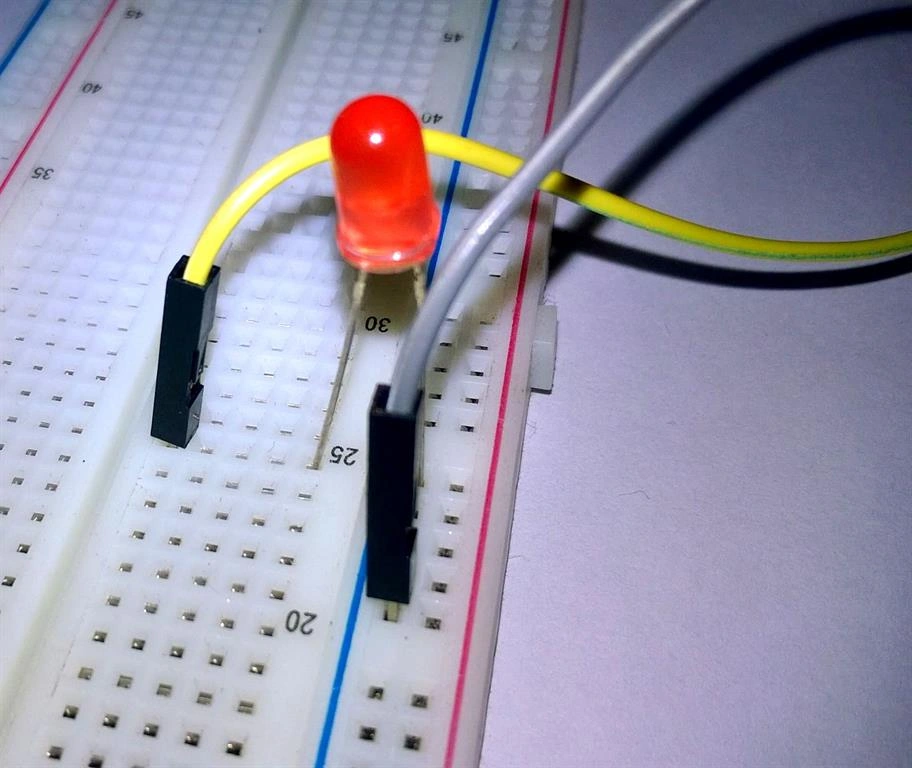
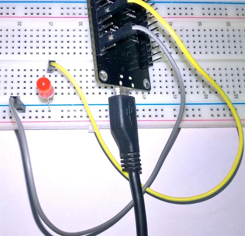
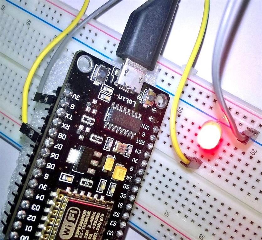
I hope this Graphic illustration will be sufficient. But, in case these images don't load properly (due to slow network connections, etc.), you
can refer to the connection profile below.
Connection Profile:
- Connect D7 pin (GPIO13 of NodeMcu) to the long leg of the LED (the positive leg, called the anode).
- Connect G(Ground)pin of NodeMcu to the short leg of the LED (the negative leg, called the cathode)
- Now, come back to the ArduinoIDE. You need to set up your preferences.
- (File > Preferences)
- Copy this URL and paste it in the Additional Boards Manager URLs option.

- void setup()
- {
- // initialize digital pin 13 as an output.
- pinMode(13, OUTPUT);
- }
- // the loop function runs over and over again forever
- void loop() {
- digitalWrite(13, HIGH); // turn the LED on (HIGH is the voltage level)
- delay(1000); // wait for a second
- digitalWrite(13, LOW); // turn the LED off by making the voltage LOW
- delay(1000); // wait for a second
- }
Next, run the code. And your job's done!

Congratulations! You've successfully interfaced with an ESP NodeMcu...and even Blinked an LED!
Read more articles on Internet of Things (IoT):
Dheeraj ChumblePosted Aug 28, 2018, 2:55 AM
Hello. May i ask for some help. I have followed all the steps to add NodeMCU in arduino IDE 1.8.6. However i am still getting an "Error compiling for board NodeMCU 1.0(ESP 12E Module)", moreover i am unable to add Arduino Master zip library in arduino ide. It says this is not a valid library. I got stuck in these two errors since so many days. Plz somebody help me out. My mail id: "[email protected]"
Hadshana KamalanathanPosted Jul 21, 2018, 11:53 AM
Nice Article
Alvaro PiffarettiPosted Apr 11, 2018, 7:50 PM
Please use a resistor for Led connection, it's a good practice, it's good to show proper handling of ICs.
JAYARAJPosted Apr 3, 2018, 7:39 AM
Also pl advice node mcu and ardino was diffrent plot form hence why you used both litle bit confused. also c# coding was not running ! why used the microgear name sace.
JAYARAJPosted Apr 3, 2018, 7:37 AM
I have some clarification . whether you used the wifi network or USB
JAYARAJPosted Apr 3, 2018, 7:36 AM
Hiave some clarification
Pascal HernandezPosted Feb 7, 2018, 6:53 PM
Hello, do you know where could we download the schematic from this board?
Mike BoltonPosted Jan 12, 2018, 7:23 AM
My first LoLin NodeMCU V3 board didn't work at all. The second connected OK via COM3. Drivers are OK. Board selected OK. COM port OK. Uploaded the 'blink' program. Got loads of error messages. Blue LED kept flashing. Espcomm_send_command(FLASH_DOWNLOAD_DATA) failed. Also 'wrong direction/ command: 0x01 0x03, expected 0x01 0x04. ' Something wrong here, but what?
Truth SeekerPosted Dec 11, 2017, 12:32 PM
I have a question about preparing the board that I did not see in your tutorial. CH341SER.zip I understand is the driver needed, that I installed, good. ESPlorer.zip Is a tool used to flash something to the module?LuaLoader.zip This is firmware? Needed so the module can be programmed with your sketch in arduino ide? You do not explain any of this, I am confused what to do with this file.
ravendra singhPosted Nov 14, 2017, 4:39 AM
Please make program for me connect 8ch relay with esp8266 e12
K CPosted Dec 19, 2016, 9:15 PM
You directly connect an led to the gpio output? no resistor needed to limit the current?
Srijith JayakumarPosted Jul 20, 2016, 10:04 AM
Thanks for the step. Blink working great
Prasanna MuraliPosted May 20, 2016, 10:14 AM
Nice one...
Mohammed IbrahimPosted Mar 14, 2016, 4:01 AM
nice
Debasis SahaPosted Mar 14, 2016, 12:47 AM
Nice share
Asfend YarPosted Mar 13, 2016, 2:02 PM
good job
Kumaresh RajalingamPosted Mar 11, 2016, 8:20 PM
Good start keep it up..
Ammar ShaukatPosted Mar 11, 2016, 5:42 PM
Electrical Engineering is not my field .. so have fun :)
Vignesh ManiPosted Mar 11, 2016, 5:40 PM
nice
Kashif SohailPosted Mar 11, 2016, 2:38 PM
nice article