

Introduction
In this article I will explain about the controlling LED using IR Remote in Arduino Mega. The LED can be turned on/off using the remote control.
Parts of list
- Arduino Mega 2560
- IR Remote
- IR sensor
- Bread Board
- Hook-Up Wires
- LED-3.
IR Remote and IR Sensor Function:
IR Remote:
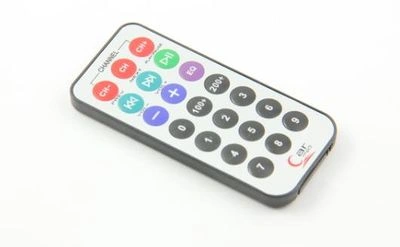
Figure 1: IR Remote
-
Remote is controlling things in particular places.
-
Remote can work in the form of a signal from the sender to the receiver parts.
Uses:
- Television
- DVD Players
- Audio Players
IR Sensor:
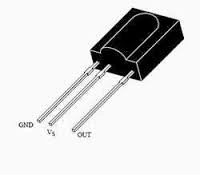
Figure 2: IR Sensor
- This sensor is the main part of the IR Remote.
- It will produce the signal to the remote.
- It can have the three pins Gnd, Vcc, Vin.
Connections:
Connection From the LED to the Arduino Mega 2560:
Take the THREE LED pin and fix in the breadboard.
First LED Connection:
- Positive pin = 02
- Negative Pin = Gnd
Second LED Connection:
- Positive pin =04.
- Negative Pin = Gnd
Third LED Connection:
- Positive pin =07
- Negative Pin = Gnd
Connection From the IR Sensor to the Arduino Mega 2560:
- The first pin is the Gnd pin connected to the Gnd of the Arduino Mega 2560.
- The second pin is the Vcc pin connected to the +5v of the Arduino Mega 2560.
- The third pin is the Vin pin connected to the digital pin 3 to the Arduino Mega 2560
Programming:
- #include <IRremote.h>
- int RECV_PIN = 3; // the pin where you connect the output pin of TSOP4838
- int led1 = 2;
- int led2 = 4;
- int led3 = 7;
- int itsONled[] = {0,0,0,0};
- #define code1 63495 // code received from button A
- #define code2 30855 // code received from button B
- #define code3 22695 // code received from button C
- IRrecv irrecv(RECV_PIN);
- decode_results results;
- void setup()
- {
- Serial.begin(9600); // you can comment this line
- irrecv.enableIRIn(); // Start the receiver
- pinMode(led1, OUTPUT);
- pinMode(led2, OUTPUT);
- pinMode(led3, OUTPUT);
- }
- void loop() {
- if (irrecv.decode(&results)) {
- unsigned int value = results.value;
- switch(value) {
- case code1:
- if(itsONled[1] == 1) { // if first led is on then
- digitalWrite(led1, LOW); // turn it off when button is pressed
- itsONled[1] = 0; // and set its state as off
- } else { // else if first led is off
- digitalWrite(led1, HIGH); // turn it on when the button is pressed
- itsONled[1] = 1; // and set its state as on
- }
- break;
- case code2:
- if(itsONled[2] == 1) {
- digitalWrite(led2, LOW);
- itsONled[2] = 0;
- } else {
- digitalWrite(led2, HIGH);
- itsONled[2] = 1;
- }
- break;
- case code3:
- if(itsONled[3] == 1) {
- digitalWrite(led3, LOW);
- itsONled[3] = 0;
- } else {
- digitalWrite(led3, HIGH);
- itsONled[3] = 1;
- }
- break;
- }
- Serial.println(value); // you can comment this line
- irrecv.resume(); // Receive the next value
- }
- }
- Before uploading the program add the library in the Arduino library.
- Click to add the library - IR Arduino library.
Explanation:
- In the section it can work under the remote control.
- To see the remote value press the button and see in the serial monitor.
- When we press button1 the led can be turn ON.
- When we press button2 the led can be turn ON.
- When we press button3 the led can be turn ON.
- Same process can be done for turning OFF the LED.
Output:

Figure 3:Output
Read more articles on Arduino:
Delpin Susai RajPosted Aug 28, 2016, 4:41 AM
Nice
Gowtham RajamanickamPosted Apr 19, 2016, 6:39 AM
Nice Share
Sibeesh VenuPosted Feb 15, 2016, 12:37 AM
Nice Share
Mohammed IbrahimPosted Feb 14, 2016, 11:27 PM
nice
Gowtham KPosted Feb 13, 2016, 11:30 AM
Good one, Thanks for sharing:)
Kumaresh RajalingamPosted Feb 13, 2016, 4:32 AM
Thank u shubham sir
Kumaresh RajalingamPosted Feb 13, 2016, 4:32 AM
Thank u santhakumar sir
Kumaresh RajalingamPosted Feb 13, 2016, 4:32 AM
No only IDE is available https://www.arduino.cc/en/Main/Software
Talha Bin AfzalPosted Feb 13, 2016, 4:24 AM
Is there any arduino emulator available?
Santhakumar MunuswamyPosted Feb 13, 2016, 2:58 AM
Thanks for nice share
Shubham KumarPosted Feb 13, 2016, 1:19 AM
nice
Kumaresh RajalingamPosted Feb 13, 2016, 12:30 AM
Thanks Pramod Sir
Pramod ThakurPosted Feb 13, 2016, 12:30 AM
Thanks for shaing..
Kumaresh RajalingamPosted Feb 12, 2016, 8:24 PM
Thanks SR
Sr KarthigaPosted Feb 12, 2016, 7:42 PM
Good one