

In this article, we will discuss how to create dashed lines in Path Geometrics in WPF and how we create Transforming shapes In WPF.
Dashed line
Now we create a dashed line in WPF. For this follow these steps:
Step1: First we create a Path tag:
<Path Stroke="Red" StrokeThickness="2"> </Path>
Here we set its color Red and set its thickness to "2".
Step 2: After that we create a <PathGeometry> and <PathFigure> tag in it.
<Path Stroke="Red" StrokeThickness="2">
<Path.Data>
<PathGeometry>
<PathFigure StartPoint="0,90" >
<LineSegment Point="10,90" />
</PathFigure>
<PathFigure StartPoint="15,90" >
<LineSegment Point="30,90" />
</PathFigure>
<PathFigure StartPoint="35,90" >
<LineSegment Point="50,90" />
</PathFigure>
<PathFigure StartPoint="55,90" >
<LineSegment Point="70,90" />
</PathFigure>
<PathFigure StartPoint="45,90" >
<LineSegment Point="50,90" />
</PathFigure>
</PathGeometry>
</Path.Data>
</Path>
Here we use LineSegment to create the line. And set the StartPoint of the <PathFigure> tag.
The Output will be: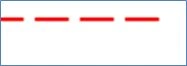
Transforming Shapes in WPF
Now we take an example of Transforming Shapes In WPF. For this follow these steps:
Step 1: First we create a PolyLine tag like this and set the RotateTransform tag in it and set its value in it:
<Polyline Points="5,25 0,50 25,75 50,50 25,25 25,0"
Stroke="Red" StrokeThickness="10"
Canvas.Left="105" Canvas.Top="50" Margin="6,125,0,40" HorizontalAlignment="Left" Width="113">
<Polyline.RenderTransform>
<RotateTransform CenterX="50" CenterY="50" Angle="45" />
</Polyline.RenderTransform>
</Polyline>
Output: 
Step 2: Now we change the angle:
<Polyline
Points="5,25 0,50 25,75 50,50 25,25 25,0"
Stroke="Red" StrokeThickness="10"
Canvas.Left="75" Canvas.Top="50"
RenderTransformOrigin="0.5,0.5" Height="86" VerticalAlignment="Bottom" Margin="63,0,66,36">
<Polyline.RenderTransform>
<RotateTransform Angle="90" />
</Polyline.RenderTransform>
</Polyline>
Output: 
Again we change the angle:
<Polyline
Points="5,25 0,50 25,75 50,50 25,25 25,0"
Stroke="Red" StrokeThickness="10"
Canvas.Left="75" Canvas.Top="50"
RenderTransformOrigin="0.5,0.5" Margin="109,87,20,89">
<Polyline.RenderTransform>
<RotateTransform Angle="180" />
</Polyline.RenderTransform>
</Polyline>
<Polyline
Points="5,25 0,50 25,75 50,50 25,25 25,0"
Stroke="Red" StrokeThickness="10"
Canvas.Left="75" Canvas.Top="50"
RenderTransformOrigin="0.5,0.5" Margin="13,132,116,44">
<Polyline.RenderTransform>
<RotateTransform Angle="280" />
</Polyline.RenderTransform>
</Polyline>
Output: 
<Polyline
Points="5,25 0,50 25,75 50,50 25,25 25,0"
Stroke="Red" StrokeThickness="10"
Canvas.Left="75" Canvas.Top="50"
RenderTransformOrigin="0.5,0.5" Margin="0,0,-45,-22" Height="110" HorizontalAlignment="Right" VerticalAlignment="Bottom" Width="161">
<Polyline.RenderTransform>
<RotateTransform Angle="360" />
</Polyline.RenderTransform>
</Polyline>
Output: 
Output of the Whole Program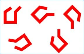
Join the conversation! Your thoughts help the community grow.