

Introduction
- In this article, I will explain about displaying RGB Light With Arduino Mega 2560.
- It can be used to change according to the colored paper.
- It can work under the color sensor.
Parts Of Lists:
- Arduino Mega 2560
- LED-3
- Color sensor
- Hookup Wires
Color Sensor:
- The color sensor can be used to convert the light to a frequency converter.
- It can be used to filter the RGB color.
- We will calculate the RGB color value.
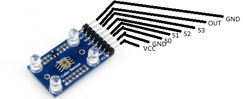 Figure 1: Color sensor.
Connection:
Step 1: Connection From Color Sensor To Arduino Mega 2560:
- Connect the S0 pin to the GND of the Arduino board.
- Connect the S1 pin to the VCC of the 5V Arduino board.
- Connect the S2 pin to the 03 of the Arduino board.
- Connect the S3 pin to the 04 of the Arduino board.
- Connect the S0 pin to the 05 of the Arduino board.
- Connect the VCC pin to the 5V of the Arduino board.
- Connect the GND pin to the GND of the Arduino board.
Step 2: Connection From LED To Arduino Mega 2560:
LED 1: RED Color:
- Positive pin to the 13.
- Negative pin to the GND.
LED 2: GREEN Color:
- Positive pin to the 12.
- Negative pin to the GND.
LED 3: BLUE Color:
- Positive pin to the 11.
- Negative pin to the GND.
Programming:
- int redPin=13; // red ping
- int greenPin=12; // green pin
- int bluePin=11; // blue pin
- int S2=03; // Color sensore pin S2 to Arduino pin 7
- int S3=04; // Color sensor pin S3 to Arduino pin 8
- int outPin=05; // color Sensor OUT to Arduino pin 4
- int rColorStrength;
- int gColorStrength;
- int bcolorStrength;
- unsigned int pulseWidth;
- void setup() {
- Serial.begin (9600); //Turn on serial port
- pinMode(redPin, OUTPUT);
- pinMode(greenPin, OUTPUT);
- pinMode(bluePin, OUTPUT);
- pinMode(S2, OUTPUT);
- pinMode(S3, OUTPUT);
- pinMode(outPin, INPUT);
- }
- void loop() {
- // Lets star by reading Red component of the color
- // S2 and S3 should be set LOW
- digitalWrite(S2,LOW);
- digitalWrite(S3,LOW);
- pulseWidth = pulseIn(outPin,LOW);
- rColorStrength = pulseWidth/400. -1;
- rColorStrength = (255- rColorStrength);
- // Lets read green component of the color
- // S2 and S3 should be set LOW
- digitalWrite (S2,HIGH);
- digitalWrite (S3,HIGH);
- pulseWidth = pulseIn(outPin,LOW);
- gColorStrength = pulseWidth/400. -1;
- gColorStrength = (255- gColorStrength);
- // Let's read blue component of the color
- // S2 and S3 should be set LOW and HIGH Respectively
- digitalWrite(S2,LOW);
- digitalWrite(S3,HIGH);
- pulseWidth = pulseIn(outPin,LOW);
- bcolorStrength = pulseWidth/400. -1;
- bcolorStrength = (255- bcolorStrength);
- Serial.print(rColorStrength);
- Serial.print(“, “);
- Serial.print(gColorStrength);
- Serial.print(“, “);
- Serial.println(bcolorStrength);
- Serial.println(“ ”);
- if (rcolorstrength>bcolorstrength &&rcolorstrength>gcolorstrength){
- digitalwrite(redpin,HIGH);
- digitalwrite(bluepin,LOW);
- digitalwrite(greenpin,LOW);
- }
- if (gcolorstrength>bcolorstrength &&gcolorstrength>rcolorstrength){
- digitalwrite(redpin,LOW);
- digitalwrite(bluepin,LOW);
- digitalwrite(greenpin,HIGH);
- }
- if (bcolorstrength>rcolorstrength &&bcolorstrength>gcolorstrength){
- digitalwrite(redpin,LOW);
- digitalwrite(bluepin,HIGH);
- digitalwrite(greenpin,LOW);
- }
- delay(250);
- }
- In this article I have explained about displaying RGB color in the Arduinomega2560.
- It changes when the color is shown near the sensor and reflected in the LED.
- The color value can be seen in the serial monitor.
- For red, it will turn ON the red LED color.
- For blue, it will turn ON the blue LED color.
- For green, it will turn ON the green LED color.
Output:

Figure 2: Output
Read more articles on Arduino:
Sr KarthigaPosted May 25, 2016, 8:18 AM
thank you santhakumar sir
Sr KarthigaPosted May 25, 2016, 8:18 AM
thank you prasana
Santhakumar MunuswamyPosted May 21, 2016, 2:21 AM
Thank you for nice work
Prasanna MuraliPosted May 20, 2016, 10:04 AM
Nice one...
Sr KarthigaPosted May 3, 2016, 8:28 PM
thank you amit dave sir
Sr KarthigaPosted May 3, 2016, 8:28 PM
Thank you raja sir
Amit DavePosted May 3, 2016, 10:28 AM
Keep up the Good work!
RajaPosted May 3, 2016, 12:16 AM
Great Work..
Sr KarthigaPosted May 2, 2016, 8:56 PM
thank you vignesh sir
Sr KarthigaPosted May 2, 2016, 8:56 PM
thank you saha sir
Vignesh ManiPosted May 2, 2016, 12:00 PM
Good one
Debasis SahaPosted May 2, 2016, 10:05 AM
Nice One..
Sr KarthigaPosted May 2, 2016, 9:13 AM
thank you bhuvanesh sir
Sr KarthigaPosted May 2, 2016, 9:13 AM
Thank you sonu sis
Bhuvanesh MohankumarPosted May 2, 2016, 6:54 AM
Great
Sonu ChaudharyPosted May 2, 2016, 5:51 AM
good one
Sr KarthigaPosted May 2, 2016, 5:34 AM
thank you nitin sir
Sr KarthigaPosted May 2, 2016, 5:34 AM
you can buy in the above link
Sr KarthigaPosted May 2, 2016, 5:33 AM
http://www.ebay.in/itm/121841609220?aff_source=Sok-Goog
Sr KarthigaPosted May 2, 2016, 5:32 AM
Thank you gowtham rajamanickam sir
NitinPosted May 2, 2016, 3:32 AM
Thanks for sharing
Thiruppathi RPosted May 2, 2016, 2:27 AM
I like this..but how to buy Arduino Mega 2560?
Gowtham RajamanickamPosted May 2, 2016, 2:00 AM
good article..