

Introduction:
This project describes an approach for constructing a hardware emulation of a segmented seven element LED display. This is the same sort of numeric LED used in microwave ovens, cheap alarm clocks, and even in some not so cheap aircraft. It is most commonly used to display things such as the time, radio frequencies, how much money you have deposited into the soda machine, or just how much it is going to cost to fill up the gas tank.
Whilst it is not of any particular value to display numeric values with an LED emulation within the context of a modern software application, the control does offer some value in situations where you may wish to build a simulation of an actual piece of hardware.
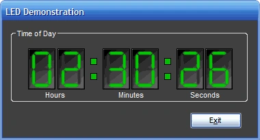
Figure 1: LED Control Demonstration
Getting Started:
In order to get started, unzip the attachment and load the solution into Visual Studio 2005. Examine the solution explorer and note that the solution contains two projects:
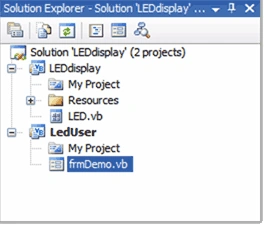
Figure 2: The Solution Explorer Showing the Project Files
The LED display project is a Windows Control Library and it contains a single user control entitled, "LED"; as might expect, this LED.vb control contains the class that defines the custom LED control. Note also that the project contains a resources folder; the resources used within this project include the images needed to display the LED's numeric values (0 through 9).
The second project, LED User, is a demonstration project that consumes the control . This project contains a single windows form class entitled, "frmDemo.vb". This form contains six LED controls which are updated every 1000 milliseconds to display the current time of day (see Figure 1).
The Code: LED.vb
The LED.vb control is a user control and as such is has a visual designer; the size of the control was set to 40 pixels wide and 60 pixels tall, a picture box control was dropped onto the container and it was set to dock to the full extent of the container.
To supply the correct visual representation of the numeric values, I merely used ten image files, one for each digit from zero to nine. I used a common drawing package to define a 40 pixel by 60 pixel drawing, gave it a slight gradient background that was mostly black, and I defined a green filled polygon of the correct size and shape to support building each segment of the seven segment LED display. To generate each number, I just ghosted out the unused LED segments by setting their fill to a dark gray color. I did this to make the segment still lightly visible much as it is in an actual LED display. Naturally, this fill color (green) could have been any color and if you are simulating a red, or amber, or cyan LED, you would want to use that color instead of green. I used green because green is the color the human eye is most adept at perceiving and because it is a color commonly used in military applications where the use of night vision imaging systems is required (greens in the 450 nanometers of wavelength range do not impair use of the NVIS devices).
To embed the necessary images into the document, I opened up "My Project" from the solution, opened the "Resources" tab, and used the interface to load each of the ten images used to supply the numeric readouts used by the control. Once added to the project; you will notice that a folder entitled, "Resources" is added to the project; if you look inside the folder, you will see each of the image files. Selecting any of the image files contained in the folder will reveal its properties in the property grid control; I selected all of the images and set the build action property to "embedded resource" although the images can still be retrieved without performing this last step.
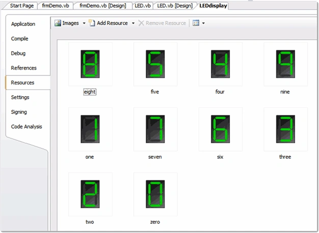
Figure 3: My Project-Adding image files to the control's resources
With the control added, and the image files packed into the control library's available resources, the only thing left to do is to write the small bit of code necessary to drive the display of the correct image in response to setting the current numeric value for the control.
The "Embed.vb" class contains only the following code:
Public Class LED
Private Sub LED_Load(ByVal sender As Object, ByVal e As System.EventArgs) Handles
Me.Load
SetNumber(0)
End Sub
Public Sub SetNumber(ByVal num As Integer)
Select Case num
Case 0
pbxLED.Image = My.Resources.zero
Case 1
pbxLED.Image = My.Resources.one
Case 2
pbxLED.Image = My.Resources.two
Case 3
pbxLED.Image = My.Resources.three
Case 4
pbxLED.Image = My.Resources.four
Case 5
pbxLED.Image = My.Resources.five
Case 6
pbxLED.Image = My.Resources.six
Case 7
pbxLED.Image = My.Resources.seven
Case 8
pbxLED.Image = My.Resources.eight
Case 9
pbxLED.Image = My.Resources.nine
Case Else
pbxLED.Image = My.Resources.zero
End Select
End Sub
End Class
As you can see, the code required to drive the display is trivial. The class contains no imports and is declared publicly. The load event handler initializes the LED emulation to display the numeric value of zero; it does this through a public subroutine entitled, "SetNumber" which in turn accepts a single integer argument representing the number that the control should display.
The "SetNumber" subroutine performs a select case on the integer value passed into the subroutine and depending upon which number was passed in, it selects and loads the appropriate image into the control's picture box control using the images contained in the control's resources.
To make the control a bit more robust, you should evaluate the integer passed into the subroutine to make sure that it is greater than or equal zero, and less than or equal to nine.
That pretty much wraps up the control. Once an instance of the control is created, the control's "SetNumber" subroutine is used to continuously update the numeric value shown in the control.
The Code: frmDemo.vb.

fahad salemPosted Nov 11, 2015, 2:14 AM
very beautiful