

Introduction
In the world of industrial automation and IoT, Modbus has long been a reliable protocol for connecting and communicating with devices in various industries. As the world transitions towards digital transformation, the integration of legacy systems like Modbus with modern cloud services is essential to unlock new possibilities for data analysis, insights, and operational efficiency. This article will explain the significance of Modbus, its compatibility with Azure IoT services, and how this integration bridges the gap between the past and the future of industrial connectivity.
What is Modbus?
Modbus is a widely used communication protocol that facilitates the exchange of data between industrial devices, sensors, and control systems. It has been the backbone of automation systems for decades, known for its simplicity and versatility. Modbus operates over serial or Ethernet connections and supports various modes, including Modbus RTU (binary) and Modbus ASCII (text-based). Its application spans industries such as manufacturing, energy, utilities, and transportation.
Integration with Azure IoT Services
Bringing Modbus into the realm of Azure IoT services opens a gateway to enhanced data processing, analytics, and management. Here's how Modbus and Azure IoT services can be compatible:
- IoT Edge Gateway: Azure IoT Edge offers an edge computing solution that can bridge the gap between Modbus devices and the cloud. By running an IoT Edge gateway on-premises, Modbus devices can communicate with the cloud without requiring significant changes to the existing infrastructure.
- Azure IoT Hub: Azure IoT Hub acts as the central hub for bi-directional communication between IoT applications and devices. By developing custom device connectors or utilizing pre-built solutions, Modbus devices can connect to Azure IoT Hub, enabling data ingestion and remote device management.
- Azure IoT Central: Azure IoT Central, a SaaS solution, simplifies the creation of IoT applications. It can be configured to connect with Modbus devices, enabling rapid deployment of custom IoT solutions without the need for extensive coding.
- Azure Functions: Leveraging Azure Functions, developers can build serverless applications that respond to Modbus device data events. This enables real-time data processing, transformation, and triggering of specific actions based on Modbus data.
Modbus Architecture
The Modbus architecture consists of several components that enable communication between master and slave devices. These components work together to facilitate data exchange, control, and synchronization in industrial automation and control systems. Here are the key components of the Modbus architecture:

1. Master Device
The master device is responsible for initiating communication with one or more slave devices. It sends queries or commands to the slaves and controls the flow of communication. Master devices can be programmable logic controllers (PLCs), industrial computers, or other devices capable of initiating Modbus communication.
2. Slave Device
Slave devices are the recipients of queries or commands sent by the master. They respond to the master's requests by providing data or executing commands. Slave devices can include sensors, actuators, drives, and other control devices.
3. Data Registers
Data registers store the actual data exchanged between master and slave devices. There are several types of data registers in Modbus.
- Coils: Coils are binary data registers that represent single bits. They are used for control purposes, such as turning devices on or off.
- Discrete Inputs: Discrete inputs are read-only binary data registers that represent the status of devices or sensors.
- Input Registers: Input registers store analog data values, such as temperature readings or sensor outputs. They are read-only.
- Holding Registers: Holding registers store analog data values that can be read from or written to by the master. They are used for configuration, control settings, and data exchange.
4. Modbus Messages
Modbus communication is based on messages that contain information about the communication request or response. There are several types of Modbus messages.
- Request Messages: Sent by the master to request data or initiate an action from the slave. These messages include function codes that specify the action to be taken (e.g., read coils, write holding registers).
- Response Messages: Sent by the slave in response to a request from the master. They contain the requested data or an acknowledgment of the action taken.
5. Function Codes
Function codes are numerical values used to indicate the type of action to be performed in a Modbus message. Each function code corresponds to a specific Modbus command, such as reading or writing data. Examples include reading coils (Function Code 01), writing single coil (Function Code 05), reading input registers (Function Code 04), and writing multiple holding registers (Function Code 16).
6. Physical Layer
The Modbus architecture operates over different physical layers based on the communication mode.
- Serial Communication (Modbus RTU and Modbus ASCII): This layer includes the RS-232, RS-422, or RS-485 physical interfaces and the corresponding electrical specifications for transmitting data in binary or ASCII format.
- Ethernet Communication (Modbus TCP/IP): Modbus TCP/IP operates over standard Ethernet networks, using TCP/IP packets to encapsulate Modbus messages for communication over local area networks (LANs) and the internet.
7. Network
The network encompasses the physical connections, cables, and devices that facilitate communication between master and slave devices. The network can be a serial network or an Ethernet network, depending on the communication mode.
8. Addressing
Each Modbus device is assigned a unique address to identify it within the network. The addressing scheme differs for coils, discrete inputs, input registers, and holding registers.
Modbus Pin Configuration
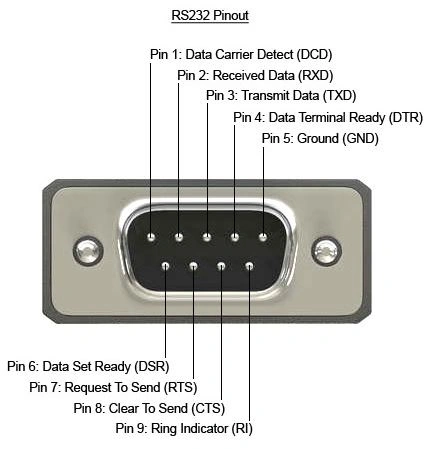
The pin configuration for Modbus communication can vary depending on the communication mode being used (Modbus RTU or Modbus ASCII) and the type of physical interface (RS-232, RS-422, or RS-485) being employed. Here, I'll provide a general overview of the pin configurations for Modbus RTU over RS-485, which is a common configuration used in industrial settings.
Modbus RTU over RS-485 Pin Configuration
RS-485 is a differential signaling standard that allows for long-distance communication and is commonly used in industrial applications. Modbus RTU is a binary protocol that uses RS-485 for communication. Below is a typical pin configuration for connecting Modbus RTU devices over RS-485:
- A (Positive or Non-Inverted Data Line): This pin carries the positive (non-inverted) signal of the differential pair. It is also known as "non-inverting" or "+".
- B (Negative or Inverted Data Line): This pin carries the negative (inverted) signal of the differential pair. It is also known as "inverting" or "-".
- Ground (GND): This pin is used to provide a common reference voltage for the communication lines and is connected to the ground reference of the system.
- Shield (Optional): In noisy environments, a shielded cable can be used to reduce electromagnetic interference. The shield is connected to the metal housing or chassis of the devices.
Connecting Modbus RTU Devices
To connect Modbus RTU devices using RS-485, you typically need to follow these steps:
Connect the "A" pin of one device to the "A" pin of the other device.
Connect the "B" pin of one device to the "B" pin of the other device.
Connect the Ground ("GND") pin of both devices to the common ground of the system.
Optionally, connect the shield wires of the cables to the metal housing or chassis of the devices to reduce interference.
Termination
For reliable communication, especially over longer distances, it's common to add termination resistors to the communication lines. Termination resistors (120 ohms) are typically connected across the "A" and "B" lines at both ends of the communication bus. This helps reduce signal reflections and ensures proper signal integrity.
Benefits of Modbus and Azure IoT Integration
- Data-Driven Insights: Integrating Modbus with Azure IoT services allows businesses to harness the power of data analytics, gaining actionable insights from real-time device data. This enables predictive maintenance, performance optimization, and data-driven decision-making.
- Scalability: Azure's cloud infrastructure ensures that as the number of Modbus devices increases, the system can scale seamlessly to accommodate the growing data load.
- Real-Time Monitoring: With the integration, businesses can monitor their Modbus devices in real-time, receive alerts for anomalies, and take immediate actions, preventing downtime and improving operational efficiency.
- Global Connectivity: Azure IoT services enable global device connectivity, making it possible to monitor and manage Modbus devices across different geographical locations.
Conclusion
The integration of Modbus with Azure IoT services marks a pivotal juncture in the evolution of industrial connectivity. By combining the legacy reliability of Modbus with the scalability, analytics, and agility of Azure IoT services, organizations can drive digital transformation, streamline operations, and uncover valuable insights from their existing infrastructure. This integration bridges the gap between traditional industrial systems and the transformative potential of the cloud, allowing businesses to transition seamlessly into the era of data-driven decision-making and IoT innovation. As the world continues to evolve, the compatibility of Modbus with Azure IoT services stands as a testament to the harmony between legacy and modern technology, shaping a future where efficiency and innovation coexist.
Saravanan GanesanPosted Aug 22, 2023, 12:19 PM
Thank you Janarthanan Selvaraj !!!!
Janarthanan SPosted Aug 22, 2023, 11:41 AM
Excellent and very detailed article Saravanan