

Introduction
- Raspberry Pi2 with installed version 10.0.10240.0 with power cable.
- HDMI cable so as to connect the Raspberry Pi2 to a monitor.
- Monitor with HDMI input.
- Ethernet cable.
- Breadboard, which is the necessary basis for mounting components and electrical wiring.
- Jumper male-male and male-female.
- Analog temperature sensor TMP36.
- MCP3008 ADC converter.
A brief mention on the chip MCP3008
The datasheet you found at this link, it is an analog/digital converter powered at a voltage of 5 v DC max, 10-bit resolution. The following are the main features.
- 10-bit resolution
- ± 1 LSB max DNL
- ± 1 LSB max INL
- 4 (MCP3004) or 8 (MCP3008) input channels.
- Analog inputs are programmable as single-ended or pseudo-differential pairs.
- On-chip sample and hold
- SPI serial interface (modes 0,0 and 1,1)
- Single supply operation: 2.7V - 5.5V
- 200 kbps max. sampling rate at VDD = 5V
- 75 kbps max. sampling rate at VDD = 2.7V
- Low power CMOS technology
- 5 nA typical standby current, 2 uA max.
- 500 uA max. active current at 5V
- Industrial temp range: -40 ° C to + 85 ° C • Available in PDIP, SOIC and TSSOP packages.
We can observe that the type of communication with the raspberry occurs through SPI protocol. Here's the pin.
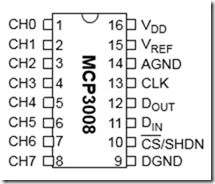 Starting from pin 1 to pin 8, we have Channels form CH0 to CH7, where we will connect the output of / Analog sensors. Each channel as we shall see must be configured by following the manufacturer's instructions as per the attached datasheet. The pins 16-15 are connected to the positive pins 14-9 to zero volts (or Ground of the Raspberry Pi2). The pins on pins 13-12-11-10 on bus SPI0 or SPI1 Raspberry Pi2.
Electrical / electronic circuit
The following is the final circuit of our project, undertaken with Fritzing, excellent software for the creation of patterns electrical/electronic.
Starting from pin 1 to pin 8, we have Channels form CH0 to CH7, where we will connect the output of / Analog sensors. Each channel as we shall see must be configured by following the manufacturer's instructions as per the attached datasheet. The pins 16-15 are connected to the positive pins 14-9 to zero volts (or Ground of the Raspberry Pi2). The pins on pins 13-12-11-10 on bus SPI0 or SPI1 Raspberry Pi2.
Electrical / electronic circuit
The following is the final circuit of our project, undertaken with Fritzing, excellent software for the creation of patterns electrical/electronic.
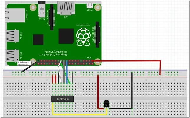 Not to be confused in the electrical connections, see below how to connect the GPIO with the MCP 3008. Observing figure 1, we see that between the pins 1 and 16 we have a sign of recognition, by turning the component by 90 ° counterclockwise, pin 1 will be the one at the bottom left, pin 8 is the one on the bottom right, the top right 9 and 16 in the upper left.
Figure 1: The pin MCP3008
Figure 2: The electronic circuit
- PIN 16 MCP3008 ----> 3.3V DC (RED CABLE)
- PIN 15 MCP3008 ----> 3.3V DC (RED CABLE)
- PIN 14 MCP3008 ----> GND (BLACK CABLE)
- PIN 13 MCP3008 ----> SPIO_SCLK (RED CABLE)
- PIN 12 MCP3008 ----> SPIO_MISO (CABLE GREY)
- PIN 11 MCP3008 ----> SPIO_MOSI (BLUE WIRE)
- PIN 10 MCP3008 ----> SPIO_CE0_N DC (GREEN LEAD)
- PIN 9 MCP3008 ----> GND (BLACK CABLE)
- PIN 1 MCP3008 ----> PIN SENSOR VOUT TMP36 DC (YELLOW CABLE)
These are connections chip MCP3008 with the card Raspberry Pi2.
Temperature Sensor TMP36
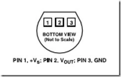 It is an analog temperature sensor, which supplies a voltage value of 10mV for degree directly proportional to the temperature value which is detected. It has a reading range that goes from -40 to 125 ° C. Here's how to connect it. Looking at the picture above, we see that it has three pins, the first on the left (1) connect me to the voltage of 3.3 v DC, the center pin (2) as shown on the input CH0 of the MPC3008, the pin right (3) on GND.
Figure 3: Pinout Sensor TMP36
- PIN LEFT TMP36 ----> 3.3V DC (RED CABLE)
- PIN CENTRAL TMP36 ----> ON PIN 1 MCP3008 (YELLOW CABLE)
- PIN RIGHT TMP36 ----> GND (BLACK CABLE)
Create the test project with Visual Studio 2015
Once the hardware part, the materials needed for the components and their characteristics, and now time to focus on the software side. We will use Visual Studio 2015. If you have not been carried out and, besides Visual Studio 2015 and Windows 10 (at least the Professional version), you must download and install the SDK for the development of Windows 10 that find this link. After installation finishes, we start Visual Studio 2015 and create using the File, New Project application using the blank template app (Windows Universal) as shown and call the project "AnalogTemperature".
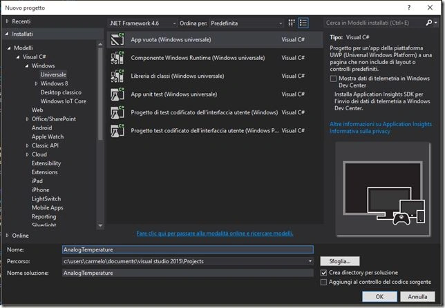 Confirm with the OK button. A project created to develop within the IoT, we need the necessary libraries. In exploring solutions position the cursor to the "References", right-click select "Add Reference” and the subsequent screens to the "Extensions" select Windows IoT extensions for the UWP as visible in the next picture.
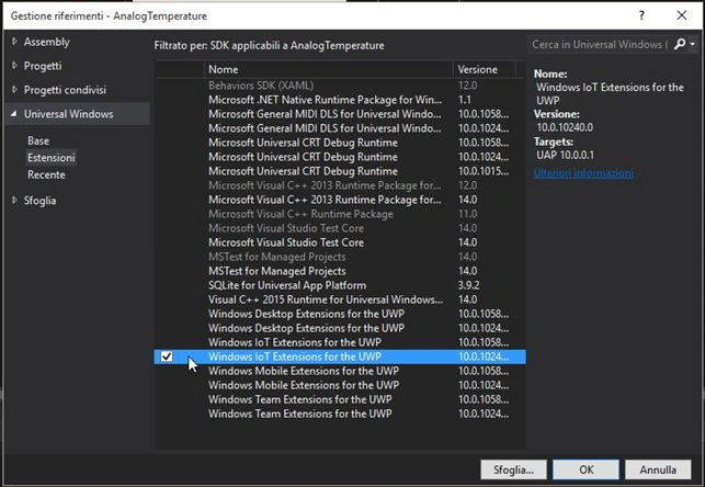 In terms of extensions, we have everything you need. We now need to create a couple of classes that will serve for the management of the sensor TMP36 and MCP 3008.
Creating Classes MCP3008 and TMP36
In exploring solutions, we place the cursor on the project name, right-click and choose "Insert" and right after "Class" and we call the MCP3008 as a chip. In the same way, we create a class called TMP36. Within the class, MCP3008 insert the following code,
In terms of extensions, we have everything you need. We now need to create a couple of classes that will serve for the management of the sensor TMP36 and MCP 3008.
Creating Classes MCP3008 and TMP36
In exploring solutions, we place the cursor on the project name, right-click and choose "Insert" and right after "Class" and we call the MCP3008 as a chip. In the same way, we create a class called TMP36. Within the class, MCP3008 insert the following code,
Let's analyze the code above. They have defined variables at the class level. The first is nothing but the base class for testing and managing device connected to / and SPI ports of GPIO.
Figure 4: New screen project
Figure 5: Management screen references
- using System;
- using Windows.Devices.Enumeration;
- using Windows.Devices.Spi;
- using Windows.UI.Popups;
- namespace AnalogTemperature
- {
- public class MCP3008
- {
- SpiDevice _device;
- TMP36 _TMP36 = new TMP36();
- string _CHOICECHANNEL;
- const double _MAXVALUE = 1023.0;
- const int _MINVALUE = 0;
- const int _RESOLUTIONBITS = 10;
- const int _SHIFTBYTE = 8;
- byte[] _CH0 = new byte[]
- {
- 1,
- 0x80,
- 0
- };
- byte[] _CH1 = new byte[]
- {
- 1,
- 0x90,
- 0
- };
- byte[] _CH2 = new byte[]
- {
- 1,
- 0xA0,
- 0
- };
- byte[] _CH3 = new byte[]
- {
- 1,
- 0xB0,
- 0
- };
- byte[] _CH4 = new byte[]
- {
- 1,
- 0xC0,
- 0
- };
- byte[] _CH5 = new byte[]
- {
- 1,
- 0xD0,
- 0
- };
- byte[] _CH6 = new byte[]
- {
- 1,
- 0xE0,
- 0
- };
- byte[] _CH7 = new byte[]
- {
- 1,
- 0xF0,
- 0
- };
- byte[] _DATARECEIVED = new byte[]
- {
- 0,
- 0,
- 0
- };
- public async void InitializeMCP3008(SerialComunication serialcomunication, Channel channel, SpiComunication spicomunication, SpiMode mode)
- {
- var spiconnectionsettings = new SpiConnectionSettings((int) Spicomunication);
- spiconnectionsettings.ClockFrequency = _TMP36.CLOCK_SIGNAL;
- spiconnectionsettings.Mode = mode;
- string spiDevice = SpiDevice.GetDeviceSelector(Spicomunication.ToString());
- var deviceInformation = await DeviceInformation.FindAllAsync(SpiDevice);
- if (DeviceInformation != null && DeviceInformation.Count > 0)
- {
- _device = await SpiDevice.FromIdAsync(DeviceInformation[0].id, spiconnectionsettings);
- _CHOICECHANNEL = Channel.ToString();
- }
- else
- {
- var dialog = new MessageDialog("Device Not Found");
- await dialog.ShowAsync();
- return;
- }
- }
- public double ReturnResult()
- {
- switch (_CHOICECHANNEL)
- {
- case "CH0":
- _DEVICE.TransferFullDuplex(_CH0, _DATARECEIVED);
- break;
- case "CH1":
- _DEVICE.TransferFullDuplex(_CH1, _DATARECEIVED);
- break;
- case "CH2":
- _DEVICE.TransferFullDuplex(_CH2, _DATARECEIVED);
- break;
- case "CH3":
- _DEVICE.TransferFullDuplex(_CH3, _DATARECEIVED);
- break;
- case "CH4":
- _DEVICE.TransferFullDuplex(_CH4, _DATARECEIVED);
- break;
- case "CH5":
- _DEVICE.TransferFullDuplex(_CH5, _DATARECEIVED);
- break;
- case "CH6":
- _DEVICE.TransferFullDuplex(_CH6, _DATARECEIVED);
- break;
- case "CH7":
- _DEVICE.TransferFullDuplex(_CH7, _DATARECEIVED);
- break;
- }
- var result = ((_DATARECEIVED[1] & 0x03) << _SHIFTBYTE) + _DATARECEIVED[2];
- var mVolt = result * (_TMP36.VOLTAGE / _MAXVALUE);
- var tempCelsius = mVolt / _RESOLUTIONBITS;
- return tempCelsius;
- }
- }
- public enum SerialComunication
- {
- SINGLE_ENDED,
- DIFFERENTIAL
- }
- public enum Channel
- {
- CH0,
- CH1,
- CH2,
- CH3,
- CH4,
- CH5,
- CH6,
- CH7
- }
- public enum SpiComunication
- {
- SPI0,
- SPI1
- }
- }
- SpiDevice _device;
- TMP36 _TMP36 = new TMP36();
The variables that follow, are all features of the integrated circuit MCP3008, starting from _MAXVALUE, which will be the maximum value in a 10-bit resolution as features found in the datasheet. _MINVALUE is the minimum value, _RESOLUTIONBITS and the maximum resolution of the MCP3008, _SHIFTBYTE representing the movement of 8 bits that must be performed once acquired the values that are returned from the DOUT pin of the MCP3008. The variables from _CH0 to _CH7 represent the eight channels available where you can connect an analog component, we will use in this example the _CH0. The variable _CHOICECHANNEL, will serve to store and what channel was used and pass the byte with the correct configuration, we will see it in the method ReturnResult (). Remains _DATARECEIVED, the byte that contains the end of the bit information to be processed and displayed to the user as the detected temperature.
- string _CHOICECHANNEL;
- const double _MAXVALUE = 1023.0;
- const int _MINVALUE = 0;
- const int _RESOLUTIONBITS = 10;
- const int _SHIFTBYTE = 8;
- byte[] _CH0 = new byte[] {1, 0x80, 0};
- byte[] _CH1 = new byte[] {1, 0x90, 0};
- byte[] _CH2 = new byte[] {1, 0xA0, 0};
- byte[] _CH3 = new byte[] {1, 0xB0, 0};
- byte[] _CH4 = new byte[] {1, 0xC0, 0};
- byte[] _CH5 = new byte[] {1, 0xD0, 0};
- byte[] _CH6 = new byte[] {1, 0xE0, 0};
- byte[] _CH7 = new byte[] {1, 0xF0, 0}
- byte[] _DATARECEIVED = new byte[] {0, 0, 0};


Rodrigo Alarcón SantiniPosted Feb 27, 2019, 11:02 AM
How will this change if i need to read the data from a potentiometer like this? https://www.adafruit.com/product/356 . There is also a bug in code - private void _timer_Tick(object sender, object is) - (Identifier expected Sintax error, ',' expected)
Max SchieberPosted Jun 2, 2017, 2:59 PM
Thank you! Helped me a lot!
Sibeesh VenuPosted Dec 21, 2015, 11:59 PM
Nice Share