

Introduction
Parts
- Arduino Mega 2560.
- PIR Sensor
- GSM Module
- Buzzer
- LED
GSM
- GSM means a Global System For Mobile Communication. It is used to send and receive a message in critical areas.
- It can also act as a GSM modem.
- It can have a PIN configuration and MIC is also attached.
 Figure 1: GSM Board
PIR Sensor
- It is used to detect people moving around approximately 10m from the sensor.
- The actual range is between 5m to 12m.
- It is of high sensitivity and low noise.
 Figure 2: PIR Sensor
Connection
- Connect the RX pin of the GSM board to the 04 of Arduino Mega 2560.
- Connect the TX pin of the GSM board to the 03 of Arduino Mega 2560.
- Connect the 5V power supply to the Arduino Mega 2560.
- At last, connect the 12 DC voltage to the GSM board.
Step 2 - Arduino Mega 2560 To PIR Sensor
- In the PIR sensor, they have three pins.
- The first pin can be connected to dc voltage range as 5v.
- The second pin can be connected to the Arduino board 5 in the digital pin.
Step 3 - Arduino Mega 2560 To LED
- The Anode(+) pin can be connected to the digital pin 7 to an Arduino board.
- The cathode(-) pin can be connected to the Gnd to an Arduino board.
Step 4 - Arduino mega 2560 To Buzzer
- The red color wire can be connected to the digital pin 10 to the Arduino board.
- The black color wire can be connected to the Gnd to the Arduino board.
- We can connect both the wires in exchange.
Programming
- #include < SoftwareSerial.h >
- #include "Timer.h"
- const int PIR = 5;
- const int TC35TXD0 = 04;
- const int TC35RXD0 = 03;
- SoftwareSerial mySerial = SoftwareSerial(TC35RXD0, TC35TXD0);
- const int siren = 10;
- int count;
- Timer t;
- void setup()
- {
- pinMode(testswitch, INPUT);
- pinMode(testled, OUTPUT);
- pinMode(PIR, INPUT);
- pinMode(siren, OUTPUT);
- pinMode(TC35button, OUTPUT);
- mySerial.begin(9600);
- digitalWrite(testled, LOW);
- digitalWrite(siren, LOW);
- digitalWrite(TC35button, HIGH);
- count = 0;
- }
- void loop()
- {
- if (digitalRead(testswitch) == HIGH)
- {
- if (digitalRead(PIR) == HIGH)
- {
- digitalWrite(testled, HIGH);
- } else {
- digitalWrite(testled, LOW);
- }
- }
- if (digitalRead(testswitch) == LOW)
- {
- digitalWrite(testled, LOW);
- delay(15000);
- digitalWrite(siren, HIGH);
- delay(500);
- digitalWrite(siren, LOW);
- delay(15000);
- digitalWrite(siren, HIGH);
- delay(500);
- digitalWrite(siren, LOW);
- delay(500);
- digitalWrite(siren, HIGH);
- delay(500);
- digitalWrite(siren, LOW);
- while (count < 2)
- {
- t.update();
- }
- digitalWrite(TC35button, LOW);
- delay(1000);
- digitalWrite(TC35button, HIGH);
- delay(20000);
- mySerial.print("AT+CMGF=1\r");
- delay(1000);
- mySerial.print("AT+CMGS=\"+xxxxxxxxxxxx\"\r");
- delay(1000);
- mySerial.println("object dected ALERT!");
- mySerial.print("\r");
- delay(1000);
- mySerial.println((char) 26);
- mySerial.println();
- delay(5000);
- digitalWrite(siren, HIGH);
- delay(20000);
- digitalWrite(siren, LOW);
- delay(1800000);
- }
- }
- void checkPIR()
- {
- if (digitalRead(PIR) == HIGH)
- {
- count = count + 1;
- }
- }
- void clearPIR()
- {
- if (count >= 2) {} else
- {
- count = 0;
- }
- }
- In this article I explained about security of the system.
- It can work or function in the sensor.
- The sensor can be used to monitor the object of a person.
- It can locate the object and sends SMS to mobile. It also raises an alarm.
- It will function under the GSM Module.
Output
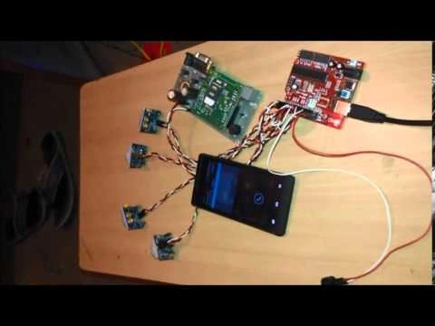
Figure 3: Output
Sr KarthigaPosted May 25, 2016, 8:13 AM
thank you santhakumar sir
Santhakumar MunuswamyPosted May 21, 2016, 2:07 AM
Thank you for nice work
Sr KarthigaPosted May 13, 2016, 10:51 AM
thank you mohammed sir
Sr KarthigaPosted May 13, 2016, 10:51 AM
thank you shidhar sir
Sr KarthigaPosted May 13, 2016, 10:50 AM
thank you raja sir
Sr KarthigaPosted May 13, 2016, 10:50 AM
thank you vignesh sir
Sr KarthigaPosted May 13, 2016, 10:49 AM
thank you sonu mam
Sr KarthigaPosted May 13, 2016, 10:28 AM
Thank you salman feris sir
Mohammed IbrahimPosted May 11, 2016, 8:17 AM
nice
Shridhar SharmaPosted May 11, 2016, 1:12 AM
very nice share.
RajaPosted May 10, 2016, 8:51 AM
Great Sharing...
Vignesh ManiPosted May 10, 2016, 8:33 AM
Nice
Sonu ChaudharyPosted May 10, 2016, 7:29 AM
great
Salman FarisPosted May 10, 2016, 4:17 AM
Nice Share sir ....