

Introduction
In the previous article Serial Class Per Universal Windows Platform - Part One, we discussed everything about the use of Serial Communication class included in Windows.Devices namespace. In this second and final part, we will create a test project with Visual Micro, a plug-in that is installed in order to program the Arduino family cards directly from Visual Studio. At the end of the first article, we created the graphical interface and the code for the management of serial communication, with the following result.
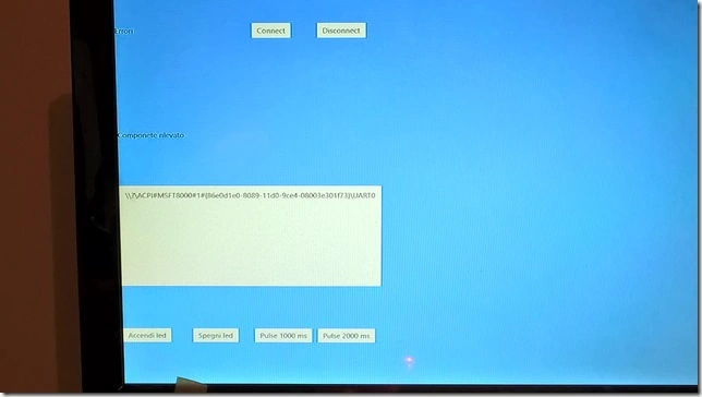
Figure 1: The final project created with Visual Studio 2015.
Test project
We start with Visual Studio 2015, select New Project from the File menu, select from the installed templates section C ++, as shown in the figure, and we call it Test serial communication.
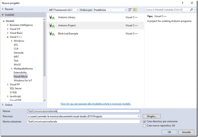
Figure 2: The test project with Visual Micro.
We confirm with OK, and we are led to the code, as shown in the figure.
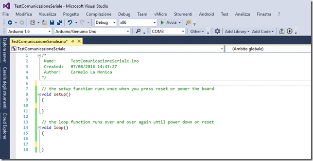
Figure 3: The TestComunicazioneSeriale.ino file with Visual Micro.
We, at this point, are ready to write a short example of code for the Arduino boards. The advantage of using Visual Micro is the convenience of having intellisense that greatly simplifies code writing, the suggestion of the methods, and / or properties at the time of typing a particular object. Another step to debug our code, unlike classic Arduino IDE where neither of these things are helpful, is to highlight one thing: The debugger for Visual Micro is not included by default, but must be purchased separately. However, you have a trial where you can try it before buying if deems appropriate. Now, we write the code that does the following:
- LED off with one command called 1.
- Powering LEDs with command called 2.
- Pulse 1 second LED with command called 3.
- Pulse 2 seconds LED by command called 4.
It's really quite simple what we will do, and a deliberate choice. Now, we write the C ++ code below and comment on all phases.
- /*
- Name: TestComunicazioneSeriale.ino
- Created: 07/08/2016 14:43:27
- Author: Carmelo La Monica
- */
- char incomingByte = '0'; // for incoming serial data
- int ledPin = 13;
- // the setup function runs once when you press reset or power the board
- void setup() {
- Serial.begin(9600); // opens serial port, sets data rate to 9600 bps
- pinMode(ledPin, OUTPUT);
- }
- // the loop function runs over and over again until power down or reset
- void loop() {
- // send data only when you receive data:
- if (Serial.available() > 0) {
- // read the incoming byte:
- incomingByte = Serial.read();
- }
- if (incomingByte == '1') {
- Serial.println("LedOff");
- digitalWrite(ledPin, LOW); // sets the LED off
- incomingByte = '0';
- }
- if (incomingByte == '2') {
- Serial.println("LedOn");
- digitalWrite(ledPin, HIGH); // sets the LED on
- incomingByte = '0';
- }
- if (incomingByte == '3') {
- Serial.println("LedOn");
- digitalWrite(ledPin, HIGH); // sets the LED on
- delay(1000); // waits for a second
- Serial.println("LedOff");
- digitalWrite(ledPin, LOW); // sets the LED off
- delay(1000);
- }
- if (incomingByte == '4') {
- digitalWrite(ledPin, HIGH); // sets the LED on
- Serial.println("LedOn");
- delay(2000); // waits for a second
- digitalWrite(ledPin, LOW); // sets the LED off
- Serial.println("LedOff");
- delay(2000);
- }
- }
Vignesh ManiPosted Aug 17, 2016, 7:52 AM
Nice
Ramesh PalaniappanPosted Aug 16, 2016, 8:28 AM
Nice content