Introduction
Normally, the Cartesian coordinate system is used in transformations and projections for graphics objects. In this case, you simply specify a point using X, Y, and Z coordinates. In practice, other coordinate systems can also be applied, and are sometimes more convenient than the Cartesian coordinate system. In this article, I will discuss the spherical coordinate system in 3D space and show you how to create the shperical graphics objects in this system.
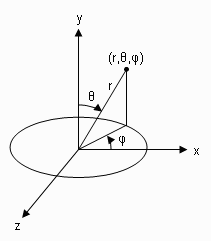
In the spherical coordinate system, a point is specified by r, θ, and φ. Here r is the distance from the point to the origin, θ is the polar angle, and φ is the azimuthal angle in the X-Z plane from the X axis. In this notation, I alternate the conventional Y and Z axes so that the computer screen is described by the X-Y plane. Figure 1 shows a point in this spherical coordinate system.

Figure 1 Spherical coordinate system
From this figure, we can obtain the following relationships

The spherical coordinates (r, θ, φ) are related to the Cartesian coordinates by

Sometimes it is more convenient to create sphere-like objects in terms of the spherical coordinate system. The following example application program will create two spheres. We need to add the Matrix3 and Point3 classes to the current project. Ans also add a new class, DrawSphere, to the project.
Now we need to add a Spherical method to the Matrix3 class. The Matrix3 class has been discussed in Chapter 5 of my new book "Practical C# Charts and Graphics".
public Point3 Spherical(float r, float theta, float phi)
{
Point3 pt = new Point3();
float snt = (float)Math.Sin(theta * Math.PI / 180);
float cnt = (float)Math.Cos(theta * Math.PI / 180);
float snp = (float)Math.Sin(phi * Math.PI / 180);
float cnp = (float)Math.Cos(phi * Math.PI / 180);
pt.X = r * snt * cnp;
pt.Y = r * cnt;
pt.Z = -r * snt * snp;
pt.W = 1;
return pt;
}
This method transforms a point in the spherical coordinate system to a point in the Cartesian coordinate system.
We then Add a DrawSphere class to the project. This class allows you to specify the radius and positions (the center location) of a sphere object. The SphereCoordinates method in this class creates the points on a sphere surface by specifying their longitude and latitude. The DrawIsometricView draws the sphere using the isometric projection.
Test the Code
This application can be tested using the following Form1 class:
using System;
using System.Drawing;
using System.Drawing.Drawing2D;
using System.Windows.Forms;
namespace Example5_6
{
public partial class Form1 : Form
{
public Form1()
{
InitializeComponent();
this.SetStyle(ControlStyles.ResizeRedraw, true);
// Subscribing to a paint eventhandler to drawingPanel:
panel1.Paint += new PaintEventHandler(panel1Paint);
}
private void panel1Paint(object sender, PaintEventArgs e)
{
Graphics g = e.Graphics;
g.SmoothingMode = SmoothingMode.AntiAlias;
float a = panel1.Height / 3;
DrawSphere ds = new DrawSphere(this, a, 0, 0, -a / 2);
ds.DrawIsometricView(g);
ds = new DrawSphere(this, 2 * a / 3, -a/2, -a/2, a / 2);
ds.DrawIsometricView(g);
}
}
}
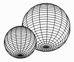
Here we create two spheres with different radii and positions. By building and running this project, you should obtain the results shown in Figure 2.

Figure 2 Spheres created in a spherical coordinate system.
This project is from the examples (example5-6 in Chapter 5) of the new book "Practical C# Charts and Graphics", where you can find more advanced chart and graphics programming for real-world .NET applications. For more information, please visit the website at www.publishing.unicadinc.com.