So far we've see transforming graphics shapes from one state to another but did you ever think about transforming colors? Why would you want to transform an image's colors? Suppose you want to provide gray scale effects, or need to reduce or increase the contrast, brightness, or redness of an image. That's when a color matrix is needed.
As we have discussed in earlier chapters, the color of each pixel of a GDI+ image or bitmap is represented by a 32-bit number where 8-bits are used for each of the red, green, blue, and alpha components. Each of the four components is a number from 0 to 255. For red, green, and blue components, 0 represents no intensity and 255 represents full intensity.
For the alpha component, 0 represents fully transparent and 255 represents fully opaque. A color vector includes four items, i.e., (R, G, B, A). The minimum values for this vector are (0, 0, 0, 0) and the maximum values for this vector are (255, 255, 255, 255).
GDI+ allows the use of values between 0 and 1 where 0 represents the minimum intensity and 1 represents the maximum intensity. These values are used in a color matrix to represent the intensity and opacity of color components. For example, the color vector with the minimum values is (0, 0, 0, 0) and the color vector with maximum values is (1, 1, 1, 1).
In color transformation, we apply a color matrix on a color vector. This can be done by multiplying a 4 x 4 matrix. However a 4 x 4 matrix supports only linear transformations such as rotation, and scaling. To perform non-linear transformations such as translation, you need to use a 5 x 5 matrix. The element of the fifth row and the fifth column of the matrix must be 1 and all of the other entries in the five columns must be 0.
The elements of the matrix are identified using a zero-based index. Thus the first element of the matrix is M[0][0] and the last element of a 5 x 5 matrix is M[4][4]. A 5x5 identity matrix is shown in Figure 10-19. In this matrix, the elements M[0][0], M[1][1], M[2][2] and M[3][3] represent the red, blue, green, and alpha factors respectively. The element M[4][4] means nothing and it must always be 1.
Now suppose you want to double the intensity of the red component of a color: simply set M[0][0] = 2. For example, the matrix shown in Figure 10-20 doubles the intensity of the red component, decreases the intensity of the green component by half, triples the intensity of the blue component, and decreases the opacity of the color by half (semi-transparent).
In the above matrix, we multiplied the intensity values. You can also add by using other matrix elements. For example, the matrix shown in Figure 10-21 will double the intensity of red component and add 0.2 to each of the red, green, and blue component intensities:
The ColorMatrix Class
In this section, we will discuss the ColorMatrix class. As you can guess from its name, this class defines a matrix of colors. In the preceding sections, we discussed the Matrix class. The ColorMatrix class is not very different from the Matrix class. The Matrix class is used in general transformation to transform graphics shapes and images, while the ColorMatrix class is specifically designed to transform colors. Before we see practical use of the color transformation, we will discuss the ColorMatrix class, its properties and methods.
The ColorMatrix class constructor takes an array, which contains the values of matrix items. The Item property of this class represents a cell of the matrix and can be used to get and set cell values. Besides the Item property, the ColorMatrix class provides 25 MatrixXY properties, which represent items of the matrix at row (X+1) and column (Y+1). MatrixXY properties can be used to get and set an item's value. Listing 10-15 creates a ColorMatrix object with item(4,4) set to 0.5 (half opacity). After that it sets the value of item (3, 4) to 0.8 and item (1, 1) to 0.3.
float[][] ptsArray ={ new float[] {1, 0, 0, 0, 0},
new float[] {0, 1, 0, 0, 0},
new float[] {0, 0, 1, 0, 0},
new float[] {0, 0, 0, 0.5f, 0},
new float[] {0, 0, 0, 0, 1}};
ColorMatrix clrMatrix = new ColorMatrix(ptsArray);
if( clrMatrix.Matrix34 <= 0.5)
{
clrMatrix.Matrix34 = 0.8f;
clrMatrix.Matrix11 = 0.3f;
}
Listing 10-15. Creating a ColorMatrix object
Now let's apply color matrices transform colors.
Matrix Operations in Image Processing
Re-coloring, the process of changing image colors, is a good example of color transformation. Re-coloring includes changing colors, intensity, contrast, and brightness of an image. It all can be done using the ImageAttribute class and its methods.
The ColorMatrix can be applied on an Image using the SetColorMatrix method of the ImageAttribute class. The ImageAttribute object is used as a parameter when you call DrawImage.
Translating Colors
Translating colors increases or decreases color intensities by a set amount (not by multiplying them). Each color component (red, green, and blue) has 255 different intensity levels ranging from 0 to 255. For example, assume the current intensity level for the red component of a color is 100. Changing its intensity level to 150 would imply translating by 50.
In a color matrix representation, the intensity varies from 0 to 1. The last row's first four elements of a color matrix represent the translation of red, green, blue, and alpha components of a color, per Figure 10-21. Hence adding a value to these elements will transform a color. For example, t1, t2, t3, and t4 values in the following color matrix represent the red, green, blue and alpha component translations:
Color Matrix ={1, 0, 0, 0, 0},{0, 1, 0, 0, 0},{0, 0, 1, 0, 0},{0, 0, 0, 1, 0},{t1, t2, t3, t4, 1}};
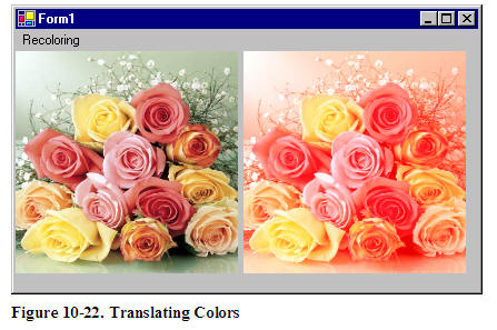
Listing 10-16 uses a ColorMatrix to translate colors. We change the current intensity of the red component to 0.90. First we create a Graphics object using the CreateGraphics method and create a Bitmap object from a file. After that we create an array of ColorMatrix elements and create a ColorMatrix from this array. Then we create an ImageAttributes object and set the color matrix using SetColorMatrix, which takes the ColorMatrix object as its first parameter. After all that we draw two images. The first image has no effects, while the second image shows the result of our color matrix transformation. Finally, we dispose the objects.
private
void TranslationMenu_Click(object sender, System.EventArgs e)
{
// Create a Graphics object
Graphics g = this.CreateGraphics();
g.Clear(this.BackColor);
// Create a Bitmap
Bitmap curBitmap = new Bitmap("roses.jpg");
// ColorMatrix elements
float[][] ptsArray =
{
new float[] {1, 0, 0, 0, 0},
new float[] {0, 1, 0, 0, 0},
new float[] {0, 0, 1, 0, 0},
new float[] {0, 0, 0, 1, 0},new float[] {.90f, .0f, .0f, .0f, 1}
};
// Create a ColorMatrix
ColorMatrix clrMatrix = new ColorMatrix(ptsArray);
// Create ImageAttributes
ImageAttributes imgAttribs = new ImageAttributes();
// Set color matrix
imgAttribs.SetColorMatrix(clrMatrix,
ColorMatrixFlag.Default,
ColorAdjustType.Default);
// Draw image with no affects
g.DrawImage(curBitmap, 0, 0, 200, 200);
// Draw image with ImageAttributes
g.DrawImage(curBitmap,
new Rectangle(205, 0, 200, 200),
0, 0, curBitmap.Width, curBitmap.Height,
GraphicsUnit.Pixel, imgAttribs) ;
// Dispose
curBitmap.Dispose();
g.Dispose();
}
Listing 10-16. Translating colors using ColorMatrix.
Listing 10-16 generates Figure 10-22. The original image is on the left, while on the right we have the results of our color translation. If you change the values of other components (red, blue, and alpha) in the last row of the ColorMatrix, you'll see different results.
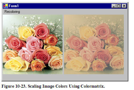
Scaling Colors
Scaling color involves multiplying a color component value by a scaling factor. For example, the t1, t2, t3, and t4 values in the following color matrix represent the red, green, blue and alpha components. If you change the value of M[2][2] to 0.5, the transformation operation will multiply the green component by 0.5, cutting its intensity by half.
Color Matrix =
{t1, 0, 0, 0, 0},
{0, t2, 0, 0, 0},
{0, 0, t3, 0, 0},
{0, 0, 0, t4, 0},
{0, 0, 0, 0, 1}};
Listing 10-17 uses the ColorMatrix to scale image colors.
private
void ScalingMenu_Click(object sender,System.EventArgs e)
{
// Create a Graphics
Graphics g = this.CreateGraphics();
g.Clear(this.BackColor);
// Create a Bitmap
Bitmap curBitmap = new Bitmap("roses.jpg");
// ColorMatrix elements
float[][] ptsArray =
{
new float[] {1, 0, 0, 0, 0},
new float[] {0, 0.8f, 0, 0, 0},
new float[] {0, 0, 0.5f, 0, 0},
new float[] {0, 0, 0, 0.5f, 0},
new float[] {0, 0, 0, 0, 1}
};
// Create a ColorMatrix
ColorMatrix clrMatrix = new ColorMatrix(ptsArray);
// Create ImageAttributes
ImageAttributes imgAttribs = new ImageAttributes();
// Set color matrix
imgAttribs.SetColorMatrix(clrMatrix,
ColorMatrixFlag.Default,
ColorAdjustType.Default);
// Draw an image with no affects
g.DrawImage(curBitmap, 0, 0, 200, 200);
// Draw Image with image attributes
g.DrawImage(curBitmap,
new Rectangle(205, 0, 200, 200),
0, 0, curBitmap.Width, curBitmap.Height,
GraphicsUnit.Pixel, imgAttribs) ;
// Dispose
curBitmap.Dispose();
g.Dispose();
}
Listing 10-17. Scaling Colors
Output from Listing 10-18 is shown in Figure 10-23. The original image is on the left, and on the right is the image after color scaling. If you change the values of t1, t2, t3, and t4, you will see different results.
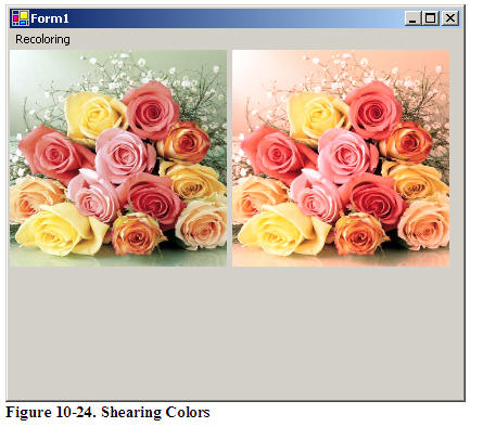
Shearing Colors
Earlier in this chapter, we saw image shearing. It can be thought of as anchoring one corner of a rectangular region and stretching the opposite corner horizontally, vertically or in both directions. Shearing colors is basically the same process, but shearing color components rather than the image itself.
Color shearing increases or decreases a color component by an amount proportional to another color component. For example, consider the transformation where the red component is increased by one half the value of the blue component. Under such a transformation, the color (0.2, 0.5, 1) would become (0.7, 0.5, 1). The new red component is 0.2 + (1/2)(1) = 0.7. The following ColorMatrix is used to shear image colors.
float
[][] ptsArray = {
new float[] {1, 0, 0, 0, 0},
new float[] {0, 1, 0, 0, 0},
new float[] {.50f, 0, 1, 0, 0},
new float[] {0, 0, 0, 1, 0},
new float[] {0, 0, 0, 0, 1}};
ColorMatrix clrMatrix = new ColorMatrix(ptsArray);
Now if you substitute this color matrix in Listing 10-17, the output will look like Figure 10-24.
Rotating Colors
Color, in GDI+ have four components: red, green, blue, and alpha. Rotating all four components in a four dimension space is hard to visualize. However it can be visualized in a three dimensional space. To do this, we drop the alpha component from the color structure and assume that there are only three colors: red, green, and blue as shown in Figure 10-25. The three colors, red, green, and blue are perpendicular to each other, so the angle between any two primary colors is 90 degrees.
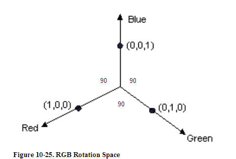
Let's say the red, green, and blue colors are represented by points (1, 0, 0), (0, 1, 0), and (0, 0, 1) respectively. If you rotate a color with green component 1, and red and blue component 0 each by 90 degrees, the new value of the color would have red component 1, and green and blue component 0 each. If you rotate less than 90 degrees, the location would be in between green and red.
Figure 10-26 shows how to initialize a color matrix to perform rotations about each of the three components: red, green, blue.
Listing 10-18 rotates the colors by 45 degrees from the red component.
private void RotationMenu_Click(object sender, System.EventArgs e)
{
float degrees = 45.0f;
double r = degrees*System.Math.PI/180;
// Create a Graphics object
Graphics g = this.CreateGraphics();
g.Clear(this.BackColor);
// Create a Bitmap from a file
Bitmap curBitmap = new Bitmap("roses.jpg");
// ColorMatrix elements
float[][] ptsArray =
{
new float[] {(float)System.Math.Cos(r),
(float)System.Math.Sin(r),0, 0, 0},
new float[] {(float)-System.Math.Sin(r),
(float)-System.Math.Cos(r),
0, 0, 0},
new float[] {.50f, 0, 1, 0, 0},
new float[] {0, 0, 0, 1, 0},
new float[] {0, 0, 0, 0, 1}
};
// Create a ColorMatrix
ColorMatrix clrMatrix = new ColorMatrix(ptsArray);
// Create ImageAttributes
ImageAttributes imgAttribs = new ImageAttributes();
// Set ColorMatrix to ImageAttributes
imgAttribs.SetColorMatrix(clrMatrix,
ColorMatrixFlag.Default,
ColorAdjustType.Default);
// Draw image with no affects
g.DrawImage(curBitmap, 0, 0, 200, 200);
// Draw image with ImageAttributes
g.DrawImage(curBitmap,
new Rectangle(205, 0, 200, 200),
0, 0, curBitmap.Width, curBitmap.Height,
GraphicsUnit.Pixel, imgAttribs) ;
// Dispose
curBitmap.Dispose();
g.Dispose();
}
Listing 10-18. Color Rotation
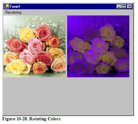
Figure 10-27 slows output from Listing 10-18. On the left is the original image, and on the right is the image after color rotation.
This articles is taken from Chapter 10 "Transformations" of Graphics Programming with GDI+.