Introduction
Here are the links for previous parts,
Blinking an LED is same as writing your first “Hello World’ program. When you set up your development environment or test a new microcontroller board the first thing you do is running a simple blink led program to see if everything is working fine and as expected.
The programs we write for LinkIt One in Arduino are called sketches. Inside the sketch we have a minimum of the following two methods:
The setup method will run once at the beginning that helps to initialize our variable and sensors. The loop method will be called repeatedly. We can have many methods other than these two.
Requirement
- LinkIt One board
- USB cable
- An LED
Connections
- Connect LinkIt One to your computer using a USB A to micro B cable.
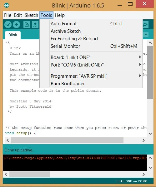
- In the Arduino IDE, go to the Tools pull-down menu at the top, select Board, and make sure “LinkIt One” is checked.
- Then pull down the Tools menu again, and select appropriate Serial Port.
If you have multiple serial ports to choose from and aren’t sure which to choose, try unplugging the board from your computer and plugging the board back again to see which port gets added.
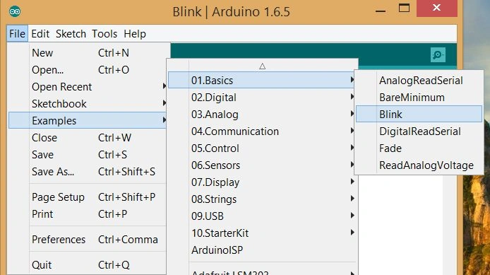
The Arduino IDE has many examples that we can use, we will run one of these now. We will test our LinkItOne with the Blink Example that you can find under
File, Examples, Basics, then
Blink.
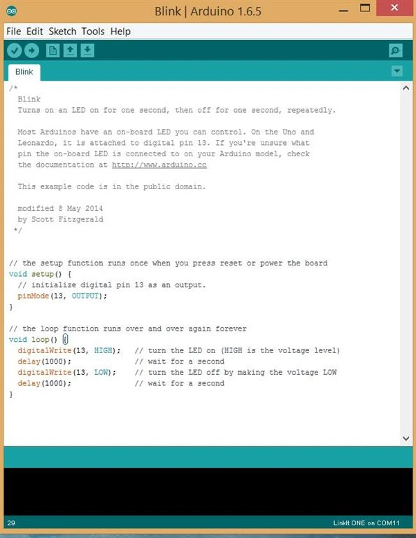
A new sketch window will open up with some code in it. Click the Upload button on the tool bar. It may take a moment to compile and upload it to the board.
When it’s done, you’ll see the text “Done uploading” at the bottom.
Code
- int led = 13;
-
- void setup()
- {
- pinMode(led, OUTPUT);
- }
-
-
- void loop()
- {
- digitalWrite(led, HIGH);
- delay(1000);
- digitalWrite(led, LOW);
- delay(1000);
- }
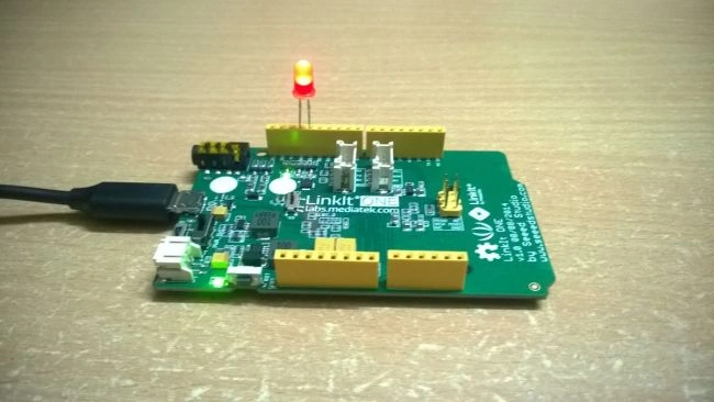
I am using a Red LED that I hooked up to pin 13 by carefully inserting the anode in pin 13 and the cathode to ground. They have polarity which means we need to connect them in the right order. There are many ways to differentiate between cathode and anode of the LED, we can tell that by looking at the LED carefully in many ways.
- The longer leg will be the cathode and the shorter will be the anode.
- When we examine the LED from the top we see the two metal posts, the smaller of the two is the anode and the bigger is the cathode.
LinkIt One has digital and analog pins for input and output. Here by default our LED is hooked up to pin 13. To compile and run the sketch just hit the upload button. In the output, you will see the transfer is complete and the LED is blinking. There is a little LED on the board that is also hooked up to pin 13 so if you don’t attach an external LED then that will also work for you.
Now we have successfully deployed our first sketch to LinkIt One. And we are ready to do more creative stuff with our powerful development board “LinkIt One”.





Nathaniel MirrenPosted Apr 25, 2018, 11:40 AM
Also doesn't it need a resistor in series to limit the current and protect the linkitone ??
Nathaniel MirrenPosted Apr 25, 2018, 11:37 AM
Not much point adding an external LED to D13 since there's already an onboard LED on that channel, you might as well put it in D8 or other, then you have 2 indicators.
Sr KarthigaPosted Jan 14, 2016, 8:22 PM
nice share
Ankit BansalPosted Dec 24, 2015, 7:40 AM
nice..
Ankur MistryPosted Dec 24, 2015, 4:08 AM
Helpful Article,
Sibeesh VenuPosted Dec 24, 2015, 3:43 AM
Nice Share
Sridhar SharmaPosted Dec 24, 2015, 3:32 AM
Nice article :)
Pooja BaraskarPosted Dec 24, 2015, 12:59 AM
Thanks Anupam Singh
Anupam SinghPosted Dec 23, 2015, 11:35 PM
Great..