

Introduction
- Raspberry Pi
- LED's
- Push Button
- Bread Board
- Hook up Wires
Traffic Lights
- Traffic lights, also known as traffic signals, traffic lamps, traffic semaphore, signal lights, stop lights, robots (in South Africa) and (in technical parlance) traffic control signals.
- The signaling devices are positioned at the road intersections, pedestrian crossings, and other locations to control the flow of traffic.
- The world's first, manually operated gas-lit traffic signal was short-lived. Installed in London in December 1868, it exploded less than a month later, injuring or killing its policeman operator.
- Traffic control started to seem necessary in the late 1890s and Earnest Sirrine from Chicago patented the first automated traffic control system in 1910. It used the words "STOP" and "PROCEED", although neither word lit up.
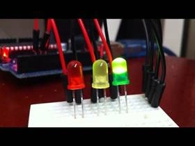
Traffic Signal Timing
- Traffic signal timing is the technique where the traffic engineers are required to determine who has the right-of-way at an intersection.
- Signal timing involves deciding how much green time the traffic lights shall provide at an intersection approach, how long the pedestrian WALK signal should be and many other numerous factors.
Connection for Traffic signal
Take the 3 LEDs for the experiment
- Led1:GPIO11
- Led2:GPIO12
- Led3:GPIO13
- Connect all the negative pins to the GND.
- Connect the SD Card with the OS and the data cable.
Programming
Explanation
- # import time and gpio modules
- import time
- import RPi.GPIO as GPIO
- # set pin 11, 12 and 13 as an outputs
- GPIO.setup(11, GPIO.OUT)# red light
- GPIO.setup(12, GPIO.OUT)# amber light
- GPIO.setup(13, GPIO.OUT)# green light
- # set pin 15 as our input
- GPIO.setup(15, GPIO.IN)# push button
- # set counters at zero
- carA = 0
- flashA = 0
- # set up a while loop so the program will keep repeating itself indefinitely
- while True: #call pin 15 button
- button = GPIO.input(15)# if button is pressed set carA as 1
- if button == False:
- carA = 1
- #if no car detected turn off green and amber lights and
- # turn on red light
- if carA == 0:
- GPIO.output(11, True)
- GPIO.output(12, False)
- GPIO.output(13, False)
- #if car detected then run through sequence
- if carA == 1: #amber light on
- GPIO.output(12, True)# wait 5 seconds
- time.sleep(5)# turn off red and amber lights
- GPIO.output(11, False)
- GPIO.output(12, False)# turn on green light
- GPIO.output(13, True)# wait 5 second
- time.sleep(5)# turn off green light
- GPIO.output(13, False)# set while loop to flash amber light 5 times
- while flashA < 5: #on, wait 5 seconds
- GPIO.output(12, True)
- time.sleep(.5)# off wait 5 seconds
- GPIO.output(12, False)
- time.sleep(.5)# add one to the flash counter
- flashA = flashA + 1# reset flash counter
- flashA = 0# reset carA
- carA = 0
- In this blog, I have explained about the traffic signal by the correct delay time.
- The output will be set as the GPIO pin and connect the push button to turnoff all the LEDs when not in use.
- The traffic signal is very useful for the real-time. The operation of traffic signals is currently limited by the data available from traditional point sensors. Point detectors can provide only limited vehicle information at a fixed location.
Output

Hadshana KamalanathanPosted Jul 21, 2018, 8:05 PM
Nice one..
Gagan SharmaPosted Nov 8, 2016, 11:52 PM
Thanks for sharing.....gud one
Anu VPosted Nov 8, 2016, 7:09 AM
Nice article..............