

Requirements
- Arduino Board
- Led
- Arduino IDE
Part 1
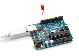
To build this circuit connect the led positive side(+) to the digital pin -13 and negative side(-) to the Gnd.
 Part 2
Connect the Arduino board to your computer through USB cable it gives the external power supply to your board
Part 3
Write the following source code to control your led ON and OFF.
Program
Part 2
Connect the Arduino board to your computer through USB cable it gives the external power supply to your board
Part 3
Write the following source code to control your led ON and OFF.
Program
Figure 1: Digital pin -13
- int led = 13;
- void setup()
- {
- Serial.begin(9600); //Baud Rate
- pinMode(led, OUTPUT);
- }
- void loop()
- {
- char data = Serial.read();
- switch (data) //Selection Control Statement
- {
- case 'ON':
- digitalWrite(led, HIGH); // Sets the led ON
- break;
- case 'OFF':
- digitalWrite(led, LOW); //Sets the led OFF
- break;
- }
- }
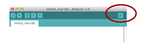
Figure 2: Arduino IDE
Set the led in the digitalpin-13 void setup() one type of function is used to initialize the variables, pinMode, etc the setup() function will run only once, after each powerup or reset of the Arduino board and void loop() it is fully based up on our conditions, how it works and what process it wants to do is called loop() function and here we are using the switch statement. It is the selection control statement based upon the condition it will work.
digitaWrite(led,HIGH) supplies 5 volts to the digital pin13 and digitalWrite(led, LOW) take the 13 pin back to the 0 volts, based upon these statements the led will generate the output.
Mengly ChrenPosted Mar 1, 2021, 10:09 AM
can you tell me how to turn on 4LED in 1pin
yahea atefPosted Nov 25, 2017, 1:06 PM
Change "OFF" to "f" and "ON" to "n" ,, it will work ;)
Gowtham RajamanickamPosted Apr 19, 2016, 6:43 AM
thanks for this article
Kumaresh RajalingamPosted Jan 6, 2016, 4:35 PM
Thank u santhakumar Sir
Santhakumar MunuswamyPosted Jan 5, 2016, 11:31 PM
Thanks for nice share
Sr KarthigaPosted Jan 4, 2016, 10:27 AM
Nice one
Kumaresh RajalingamPosted Jan 4, 2016, 6:26 AM
Thank you
Ankit BansalPosted Jan 4, 2016, 6:21 AM
Nice one..