

Introduction
- In this article, I will explain about connecting the Pulse Sensor with Android App with Arduino Mega2560.
- It can be used to give the correct information on the mobile App.
Parts of lists
- Arduino Mega 2560
- Pulse Sensor
- Bluetooth
- Hook Up wires
- Bread Boards
Pulse Sensor
- It can be used to check the pulse of the body.
- It can be user friendly and can be used by students, artists, and developers.
- It can be called the plug-play.
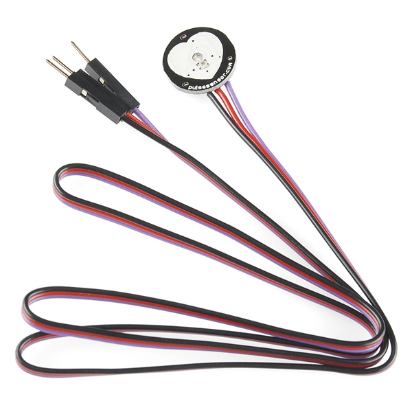 Figure 1: Pulse Sensor
Connection
Step 1 Connection from Pulse Sensor to Arduino Mega 2560
- They can commonly have three pins.
- The first pin can be connected to the gnd pin of the Arduino Mega 2560.
- The second pin can be connected to the vcc of the 5v of ArduinoMega 2560.
- The third can be connected to the vin of the Analog pin of the Ao of Arduino Mega 2560.
Step 2 Connection From Bluetooth to the Arduino Mega 2560
- Connect the vcc pin to the 5v of the Arduino Mega 2560.
- Connect the gnd pin to the gnd of the Arduino Mega 2560.
- Connect the Tx pin to the RX.
- Connect the RX pin to the TX.
Programming
Explanation
- int pulsePin = 0; // Pulse Sensor purple wire connected to analog pin 0
- int blinkPin = 13; // pin to blink led at each beat
- int fadePin = 5; // pin to do fancy classy fading blink at each beat
- int fadeRate = 0; // used to fade LED on with PWM on fadePin
- // Volatile Variables, used in the interrupt service routine!
- volatile int BPM; // int that holds raw Analog in 0. updated every 2mS
- volatile int Signal; // holds the incoming raw data
- volatile int IBI = 600; // int that holds the time interval between beats! Must be seeded!
- volatile boolean Pulse = false; // "True" when User's live heartbeat is detected. "False" when not a "live beat".
- volatile boolean QS = false; // becomes true when Arduoino finds a beat.
- // Regards Serial OutPut -- Set This Up to your needs
- static boolean serialVisual = true; // Set to 'false' by Default. Re-set to 'true' to see Arduino Serial Monitor ASCII Visual Pulse
- void setup()
- {
- pinMode(blinkPin, OUTPUT); // pin that will blink to your heartbeat!
- pinMode(fadePin, OUTPUT); // pin that will fade to your heartbeat!
- Serial.begin(115200); // we agree to talk fast!
- interruptSetup(); // sets up to read Pulse Sensor signal every 2mS
- // analogReference(EXTERNAL);
- Genotronex.begin(9600);
- Genotronex.println("Bluetooth On please press 1 or 0 blink LED ..");
- pinMode(ledpin, OUTPUT);
- }
- // Where the Magic Happens
- void loop()
- {
- serialOutput();
- if (QS == true)
- { // A Heartbeat Was Found
- // BPM and IBI have been Determined
- // Quantified Self "QS" true when arduino finds a heartbeat
- digitalWrite(blinkPin, HIGH); // Blink LED, we got a beat.
- fadeRate = 255; // Makes the LED Fade Effect Happen
- // Set 'fadeRate' Variable to 255 to fade LED with pulse
- serialOutputWhenBeatHappens(); // A Beat Happened, Output that to serial.
- QS = false; // reset the Quantified Self flag for next time
- } else
- {
- digitalWrite(blinkPin, LOW); // There is not beat, turn off pin 13 LED
- }
- ledFadeToBeat(); // Makes the LED Fade Effect Happen
- if (Genotronex.available())
- {
- BluetoothData = Genotronex.read();
- if (BluetoothData == '1')
- {
- // if number 1 pressed ....
- digitalWrite(ledpin, 1);
- Genotronex.println("LED On D12 ON ! ");
- }
- if (BluetoothData == '0')
- {
- // if number 0 pressed ....
- digitalWrite(ledpin, 0);
- Genotronex.println("LED On D12 Off ! ");
- }
- }
- delay(20); // take a break
- }
- In this article, I clearly explained about the Pulse Sensor
- It can be clearly explained in the Bluetooth app.
- When the pulse is low, it cannot blink led
- When the pulse is high, it can blink led.
Lina Roa AcevedoPosted Nov 5, 2016, 9:57 AM
Which App did you use to see the graph from pulsesensor?
Shobana JPosted Jul 8, 2016, 4:11 AM
Nice share..good one
Sr KarthigaPosted Jul 5, 2016, 10:43 AM
Thank you prasanna bro
Sr KarthigaPosted Jul 5, 2016, 10:42 AM
Thank you vignesh mani sir
Sr KarthigaPosted Jul 5, 2016, 10:42 AM
Thank you debasis sir
Sr KarthigaPosted Jul 5, 2016, 10:42 AM
Thank you santhakumar sir
Prasanna MuraliPosted Jun 21, 2016, 9:34 PM
Nice one..
Vignesh ManiPosted Jun 11, 2016, 4:46 PM
Nice one
Debasis SahaPosted Jun 10, 2016, 12:17 AM
Good one..
Santhakumar MunuswamyPosted Jun 10, 2016, 12:06 AM
Thank you for nice share