Long ago in a lifetime far away, I came across a Windows game that showed up on the screen looking very similar to a painter's palette. That is to say, the main form for the game had a shape reminiscent of a painter's palette.
That idea intrigued me so I started a little digging. The answer was so simple that I had a hard time getting behind it.
In a nutshell:
1: Visualize the shape or even draw it on paper.
2: Create a set of points (x & y Cartesian coordinates) that minimally define the outline of the intended shape.
(At this point in the process there are two ways of handling the last step)
For .net enthusiasts
3a: Declare an instance of System.Drawing.Drawing2D.GraphicsPath.
3b: Use an appropriate GraphicsPath function to add the points to the path.
3c: Set the form's Region to a new instance of Region while passing the GaphicsPath to the constructor of Region.
For old school die hards (like me)
SetWindowRgn (ByVal hWnd As Integer, ByVal hRgn As Integer, ByVal bRedraw As Boolean) As Integer
CreatePolygonRgn (ByRef lpPoint As Point, ByVal nCount As Integer, ByVal nPolyFillMode As Integer) As Integer
SetWindowRgn(Handle.ToInt32, CreatePolygonRgn(points(0), 5, 1), True)
4a: Call windows the API SetWindowRgn.
4b: For the hRgn parameter, call CreatePolygonRgn using the points defined earlier as the lpPoint parameter.
5: Sit back and let windows do the heavy lifting.
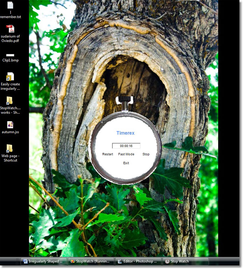
In this particular example we are going to create a Stopwatch application that actually looks like a stopwatch. First I found a simple picture of a stopwatch on the internet. Then, with a photo editor, I simply erased the face of the watch.
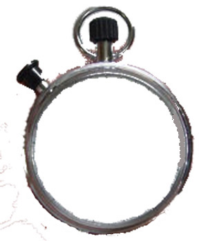
The essence of a stopwatch for me is the round body, a stem winder and a click button. For the sake of simplicity, I will 'move' the click button up onto the winder stem.
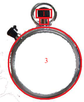
That leaves three reasonably simple geometric shapes to outline our stopwatch:
- A small square defining the winder.
- A small rectangle defining the click button / stem.
- A large circle defining the body of the watch.
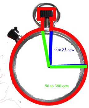
Now we need to come up with a set of points that minimally describes the outline of these three shapes combined. We can do this geometrically in four areas:
1: The curve swept out from 0 degress to 85 degress (marked green below from 3 o'clock to 12 o'clock). I had to play with the focal point and radius of the circle to closely match the size of the wath face. This uses 85 points to more closely approximate a smooth curve. Windows draws straight lines between points.
For i=0 to 85
{
Point(i).X = FocalpointX + Cos(i * (pi / 180)) * Radius
Point(i).Y = FocalpointY - Sin(i * (pi / 180)) * Radius
}
2: The next point (86) is up (down in windows coordinats) 25 units (in screen y coordinat units). The right side of the stem.
points(86).X = points(85).X
points(86).Y = points(85).Y - 25
3: The next point (87) is right 15 points. This brings us to the bottom right corner of the winder.
points(87).X = points(86).X + 15
points(87).Y = points(86).Y
4: The next point is up another 25 units. This brings us to the top right corner of the winder.
Now the Math gets easy but visualizing it is tricky
points(88).X = points(87).X
points(88).Y = points(87).Y - 25
5: I have set aside 360 points for this shape (360 degrees in a circle). So now I jump to points 96-360. Point 360 will close the circle and the shape. The arc swept out by the green radius from the bottom left of the stem to 3 o'clock on the face of the watch.
For i=96 to 360
{
Point(i).X = FocalpointX + Cos(i * (pi / 180)) * Radius
Point(i).Y = FocalpointY - Sin(i * (pi / 180)) * Radius
}
Now we work backwards from point 95 to point 89.
6: Point 95 is up (down in windows coordinates) 25 units. This brings us to the top left of the stem.
points(95).X = points(96).X
points(95).Y = points(96).Y - 25
7: Point 94 is left 15 point. This marks the bottom left of the winder.
points(94).X = points(95).X - 15
points(94).Y = points(95).Y
8: Point 93 is up 15 points. To the top left of the winder.
points(93).X = points(94).X
points(93).Y = points(94).Y - 25
Theoretically we have minimally defined the shape except that point 89 through 92 are still unset. So we just set all of them to either point 93 or point 82 (I use point 82).
For i = 89 To 92
{
points(i).X = points(88).X
points(i).Y = points(88).Y
}
Now just add these points to a graphics path and set the forms region to that path, add some timer functionality and:
C Sharp Code
Point[] points = new Point[361];
int Radius = 0;
int X = 0;
int Y = 0;
short i = 0;
X = 160;
Y = 245;
Radius = 125;
// remeber that the X, Y coordinates of a circle can be found using the sine and cosine functions from high
school trigonometry
// Start the circle at the zero angle
// and place the stem at the top say 85 degrees
// so draw that arc
for (i = 0; i <= 85; i++)
{
points[i].X = (int)(X + System.Math.Cos(i * (pi / 180)) * Radius);
// pi/180 converts degrees to radians
points[i].Y = (int)(Y - System.Math.Sin(i * (pi / 180)) * Radius);
}
// define the corners of the rectangles that define the stem
points[86].X = points[85].X;
points[86].Y = points[85].Y - 35;
points[87].X = points[86].X + 5;
points[87].Y = points[86].Y;
points[88].X = points[87].X;
points[88].Y = points[87].Y - 35;
// finish the circle
for (i = 96; i <= 360; i++)
{
points[i].X = (int)(X + System.Math.Cos(i * (pi / 180)) * Radius);
// pi/180 converts degrees to radians
points[i].Y = (int)(Y - System.Math.Sin(i * (pi / 180)) * Radius);
}
// finish the stem
points[95].X = points[96].X;
points[95].Y = points[96].Y - 35;
points[94].X = points[95].X - 5;
points[94].Y = points[95].Y;
points[93].X = points[94].X;
points[93].Y = points[94].Y - 35;
for (i = 89; i <= 92; i++)
{
points[i].X = points[88].X;
points[i].Y = points[88].Y;
}
// Old school - Windows API
//SetWindowRgn(Handle.ToInt32, CreatePolygonRgn(points(0), 360, 1), True)
//New school - .NET
GraphicsPath gPath = new GraphicsPath();
gPath.AddCurve(points);
this.Region = new Region(gPath);
Final Output: