

Flame sensor
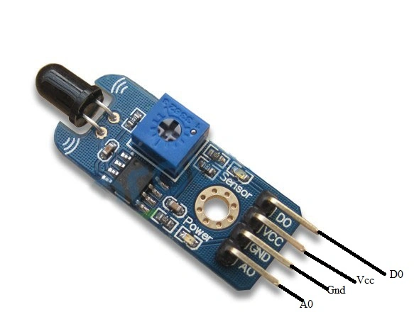
Figure 1: Flame Sensor
- It is used to detect and respond to the presence of Flame (or) Fire.
- The detected flame depends on the installation.
- We will also include sounding an alarm.
Where We Can Fix
- Schools/Colleges
- Transport
- Industrial Furnaces etc
Part Of List:
- Arduino Uno
- Flame Sensor
- Jumper Wire
- USB Cable
- Bread Board.
Connection:
Flame Sensor to Arduino:
Step 1: Vcc =Postive voltage input 5v
Step 2: A0 =Analog input pin to Arduino
Step 3: Gnd =Gnd to Gnd.
Buzzer:
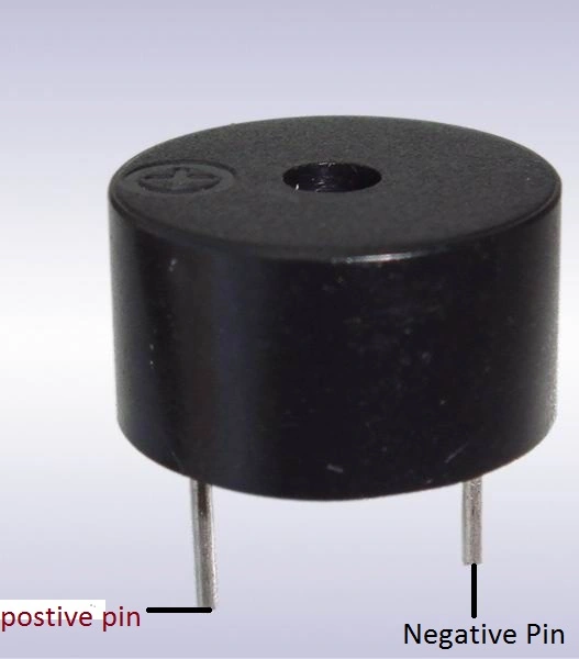
Figure 2: Buzzer.
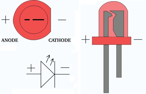
Figure 3:LED
- #include < SoftwareSerial.h >
- int sensorPin = A0; // select the input pin for the LDR
- int sensorValue = 0; // variable to store the value coming from the sensor
- int led = 2; // Output pin for LED
- int buzzer = 9; // Output pin for Buzzer
- void setup()
- {
- // declare the ledPin and buzzer as an OUTPUT:
- pinMode(led, OUTPUT);
- pinMode(buzzer, OUTPUT);
- Serial.begin(9600);
- }
- void loop()
- {
- Serial.println("Welcome to c#corner");
- sensorValue = analogRead(sensorPin);
- Serial.println(sensorValue);
- if (sensorValue < 100)
- {
- Serial.println("Fire Detected");
- Serial.println("LED on");
- digitalWrite(led, HIGH);
- digitalWrite(buzzer, HIGH);
- delay(1000);
- }
- digitalWrite(led, LOW);
- digitalWrite(buzzer, LOW);
- delay(sensorValue);
- }
- This fire can be lightly spread and it will produced a sound.
- Then automatically emergency light also gets ON.
- The value of the sensor can be see in the serial monitor.
- When Fire is detected the led can be on (HIGH).
Output
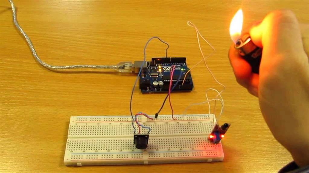
Figure 5: Output
Sr KarthigaPosted May 3, 2016, 9:06 AM
thanksfor you motivation sir
Sr KarthigaPosted May 3, 2016, 9:05 AM
thank you prashant sir
Bhuvanesh MohankumarPosted May 3, 2016, 8:22 AM
Doing great Karthiga, Keep it up
Prashant VermaPosted Mar 10, 2016, 2:11 AM
well explained
Prashant VermaPosted Mar 10, 2016, 2:10 AM
nice
khaled saidiPosted Mar 1, 2016, 9:38 PM
HI Sr karthiga plis add me in ur facebook, https://www.facebook.com/profile.php?id=100003381558280
Sr KarthigaPosted Feb 29, 2016, 8:51 AM
arduino uno
Sr KarthigaPosted Feb 29, 2016, 8:50 AM
You read first basic of electronic in this link http://101science.com/
Sr KarthigaPosted Feb 29, 2016, 8:48 AM
Thank you ehsan sie
Ehsan SajjadPosted Feb 28, 2016, 8:09 AM
interesting, I like it
siva kumarPosted Feb 13, 2016, 12:19 AM
Hi Karthiga. Am a starter in the micro processing. Which processor i need to buy for making experiments. Also please suggest some startup books for electronics.
Sr KarthigaPosted Feb 12, 2016, 7:45 PM
Thank you Shudham sir, Ankit sir, santhakumar sir
Sr KarthigaPosted Feb 7, 2016, 1:06 AM
Thank you Vignesh Mani sir
Vignesh ManiPosted Feb 6, 2016, 5:16 PM
Nice One
Sr KarthigaPosted Jan 23, 2016, 2:11 AM
Thank you sir
Santhakumar MunuswamyPosted Jan 23, 2016, 2:07 AM
Thanks for nice article
Sr KarthigaPosted Jan 22, 2016, 8:51 PM
Thanks to all
Ankit BansalPosted Jan 22, 2016, 12:55 AM
keep sharing..thanks
Shubham KumarPosted Jan 22, 2016, 12:08 AM
great
Sr KarthigaPosted Jan 21, 2016, 7:17 AM
Thank you kumaresh sir
Kumaresh RajalingamPosted Jan 21, 2016, 3:12 AM
Nice one